You have got the brand new Paloalto firewall installed, and you wanted to know how you can set up an IPsec tunnel between branches using the Paloalto firewall. If I were to configure an IPSec tunnel for the first time, I would configure them in my lab before I configure it in the production. That way, I would be well prepared before I implement them in the production.
The great thing about the Paloalto firewall is that you can spin up its VM appliance in any of the hypervisors and it supports most of the features for you to get started, there are some features that may not work well with an unlicensed version. Still, for the lab purpose, you should be good to go.
In the last blog, I covered how you can set up IPsec tunnels between the open-source firewall Pfsense, which works well for small enterprises. However Paloalto firewall is the next-gen commercial firewall, and if you are planning to work with the Paloalto firewall, you should know how to set up an IPsec VPN with it.
Read also,
How to Setup IPsec Tunnel between Paloalto and PFsense?
pfSense IPsec Site to Site VPN Setup – Step by Step.
How To Configure IPsec VPN Between pfSense And Cisco Router?
How To Configure IPsec Site-to-Site VPN On Cisco Router?
How To Configure Palo Alto Site To Site VPN Using IPsec?
What are the objectives of this lab?
- Configure the IPsec tunnel between the sites along with its policies.
- Make sure the local users can ping remote users from both branches.
- Check the connectivity using a different protocol, HTTP, for example.
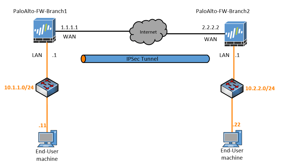
Below is the lab topology that we will configure and I am building this topology in GNS3.
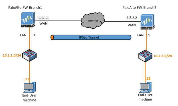
- I have two firewalls connected with the outside interface 1.1.1.1 and 2.2.2.2 on Paloalto-FW-Branch1 and Paloalto-FW-Branch2 respectively.
- On Branch1 I am using the subnet 10.1.1.0/24 and 10.2.2.0/24 for branch2.
- To simulate the internet, I am using a cisco router and below is the configuration from the Cisco routers.

- On the firewalls, the initial configuration looks like below.
| Zones | Trusted | Untrusted. |
| FW1 | 10.1.1.1 (ethernet1/2) | 1.1.1.1 (ethernet1/1) |
| FW2 | 10.2.2.1 (ethernet1/2) | 2.2.2.2 (ethernet1/1) |
- I also added default route from both firewalls towards the Internet Router.
- I am using the cisco routers for the end hosts, which has IP routing disabled and the default gateway pointed to the respective firewall inside interfaces. And below are the configurations.
Branch1-PC1.
no ip routing
ip default-gateway 10.1.1.1
ip http server
interface GigabitEthernet0/0
 ip address 10.1.1.11 255.255.255.0
Branch2-PC1
no ip routing
ip default-gateway 10.2.2.1
ip http server
interface GigabitEthernet0/0
 ip address 10.2.2.22 255.255.255.0
Note: If you are new here, and do not know how to configure Palo Alto firewall in GNS3, you may check out the below articles.
- 9 Easy steps to configure Palo-Alto firewall in Gns3
- Palo Alto Firewall Lab Setup-Allow Inside Users To The Internet
Palo alto site-to-site VPN configuration step by step.
- Check the remote reachability.
- Paloalto IPsec Phase1 configuration.
- Paloalto firewall IPsec Phase2 configuration.
- Create the Paloalto tunnel interface.
- IPsec tunnel creation.
- Configure the Static routes for the IPSec tunnel.
- Policy configuration.
- Paloalto Firewall IPsec Verification.
- Final verification.
1. Check the remote reachability.
Before you configure an IPsec tunnel, the first step is to ensure that you can reach the remote end, from each direction. By default, the Paloalto firewall would block anything coming from the outside. Let’s configure interface management profile that would allow ping and then apply it to the interface.
Again this step is not mandatory though if you are concerned about allowing ICMP on the outside interface. It would be best if you made sure end-to-end communication is reachable.
You may read the article here, where I have covered how you can allow ping for the outside interface.
As you can see, I can ping the outside interface of both the firewalls.
Branch1 firewall.
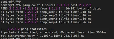
Branch2 Firewall.

Alright, we just made sure that we can reach the remote ends from both the firewalls outside IP. Let’s go ahead and start configuring the IPsec tunnels. In Paloalto it doesn’t support transport mode; it only supports tunnel mode.
Like any IPsec configuration, it starts with IPsec phase1 and then phase2.
2. Paloalto IPsec Phase1 configuration.
The phase 1 IPsec configuration includes IKE Crypto and IKE Gateway creation.
IKE Crypto Creation.
Click on Network, under Network profiles click on IKE crypto. Then click on Add.
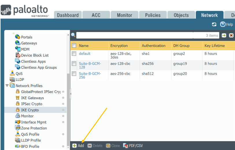
Below are the parameters that we are going to use on both the firewalls for IKE Crypto.
- Name: IKE-Crypto-Branch2. (On Fw2 – IKE-Crypto-Branch1 )
- DH Group: Group 2
- Encryption : AES-256-CBC
- Authentication: Sha-256
- Lifetime: 1 hour
The firewall 1 IKE Crypto configuration looks like below.
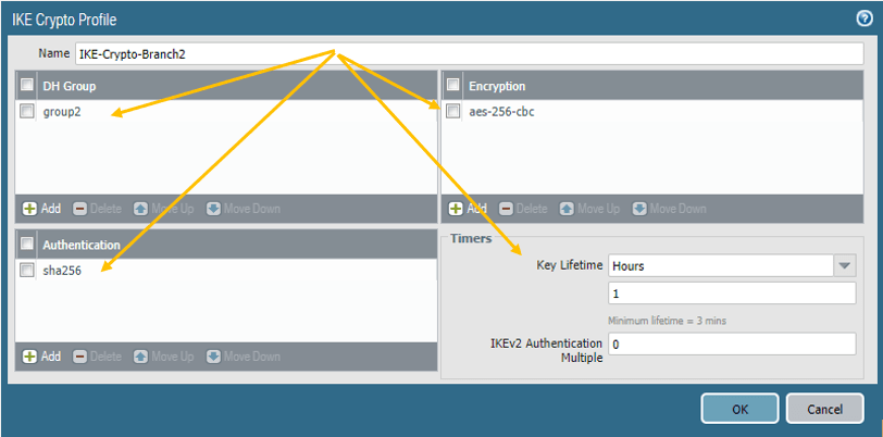
Note: Except names, all the other parameters should match on both the firewalls, else the Tunnel will not form.
We just completed the IKE Crypto configuration on both the firewall, now let’s go to the next step on the phase 2 configuration, IKE Gateways.
Creation of IKE Gateways.
The same Network profile window clicks on IKE Gateways and clicks on Add.
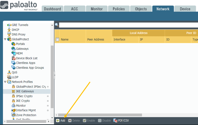
When you click on Add, there will be multiple options to fill in, first you have to fill in the IKE Gateway General and then Advanced Options.
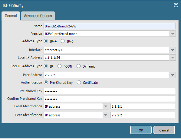
Let’s fill the IKE Gateway General options on Paloalto Firewall 1.
Below are the IKE gateway parameters that we are going to use.
Name: Branch1-Branch2-GW
Version: You can have IKEv1 only mode, or IKEv2 mode or IKEv2 preferred mode.
I am choosing the IKEv2 preferred mode.
Address Type: Since we are not using IPv6, let me select IPv4.
Interface: Choose the outside interface, which is ethernet1/1 in our setup.
Local IP address: From the drop-down list, select the firewall 1 IP address. That is 1.1.1.1/24.
Peer Address: 2.2.2.2 (Firewall2 outside IP.)
Authentication: You can have two ways of authentication in IPsec, one using a preshared Key, other is by Certificate. I am going to use the Pre-shared Key, and the Key is Paloalto.
Local Identification: Choose an IP address and type the local outside IP address of the firewall one.
You just completed the General options in the IKE gateway, and it looks like below. Next let’s go ahead and configure the Advanced Options tab under IKE Gateway.
IKE-Gateway Advanced Options.
In the Advanced Options, you can see two tabs. Each represents IKEv1 and IKEv2.
On both IKEv1 and v2, select the Crypto profile that we defined earlier.
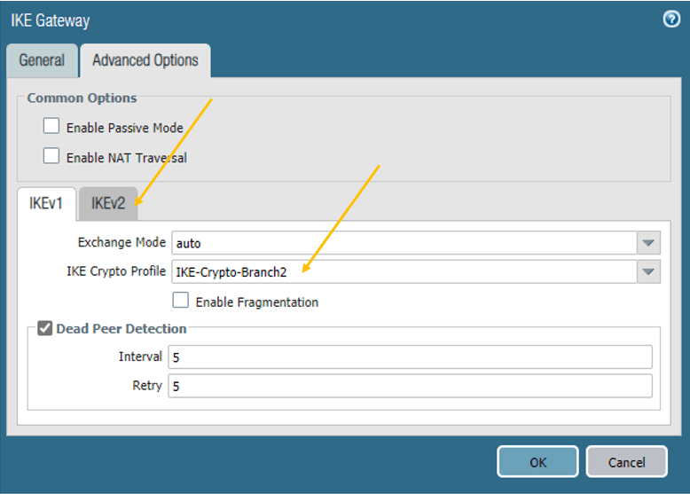
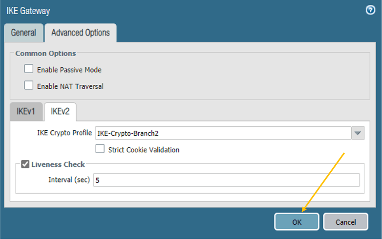
Once the Crypto profile has been selected, you may click on OK.
Note: If you are using the firewall behind NAT, then you can check the option enable NAT traversal, that is not required here as we are simulating the internet and using the Public IP on the Paloalto firewall.
We now configured the IKE Gateway on the Paloalto Firewall 1, let’s go ahead and do the same steps on the Firewall2.
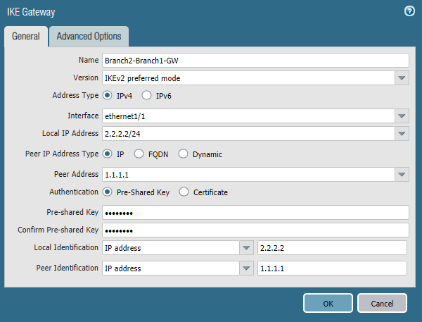
Name: Branch2-Branch1-GW
Version: IKEv2 preferred mode.
Address Type: IPv4.
Interface: Ethernet1/1
Local IP address: 2.2.2.2/24.
Peer Address: 1.1.1.1 (Firewall2 outside IP.)
Authentication(Pre-Shared Key): Paloalto.
Local Identification (IP Address): 2.2.2.2
Peer Identification(IP Address): 1.1.1.1
Advanced options.
Add the IKEv1 and V2 profiles that you have created earlier.
We have now completed the phase1 configuration of the IPsec tunnel in both the Palo Alto firewalls. Let’s go ahead and configure Phase2, which includes the IPsec Crypto and the Tunnel creation.
3. Paloalto firewall IPsec Phase2 configuration.
The first step in the Phase2 configuration is the creation of IPsec crypto.
IPSec Crypto configuration.
On the Network, tab click on the Network Profiles and click on IPSEC Crypto
Click on Add.
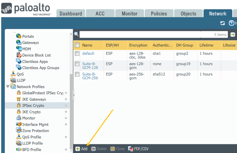
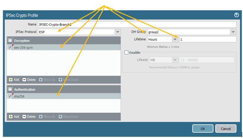
Below are the parameters that we will use for the IPsec Crypto for both Branch1 and 2.
Note: Make sure that except for the name, all the other parameters should match. Otherwise, the Tunnel won’t come up.
Name : IPSEC-Crypto-Branch2 (FW2- IPSEC-Crypto-Branch1)
Encryption : AES-256-gcm
Authentication: Sha-256
DH Group: group 2
Lifetime: 1 hour
Click OK
Below is how the IPsec Crypto configuration looks like on the Paloalto firewall 1.
4.Create the Paloalto tunnel interface.
Remember that I said, IPsec configuration on the Paloalto firewall is Tunnel based? So we need to configure a Tunnel interface that the Paloalto firewall can use to form the Tunnel.
Before you create a tunnel interface, it is recommended that you add those tunnels to a specific zone.
So let’s go ahead and create an IPsec zone on both the firewalls.
Creation of IPsec zone.
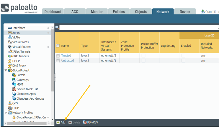
Click on Network, Zones and as you can see, I have two zones that I have created already Trusted and Untrusted.
Click on Add to add a new zone.
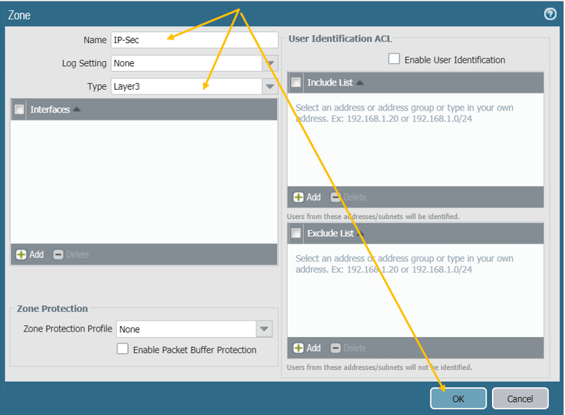
Just give the name, IP-Sec, type Layer3, and click on OK.
Create the Tunnel interface.
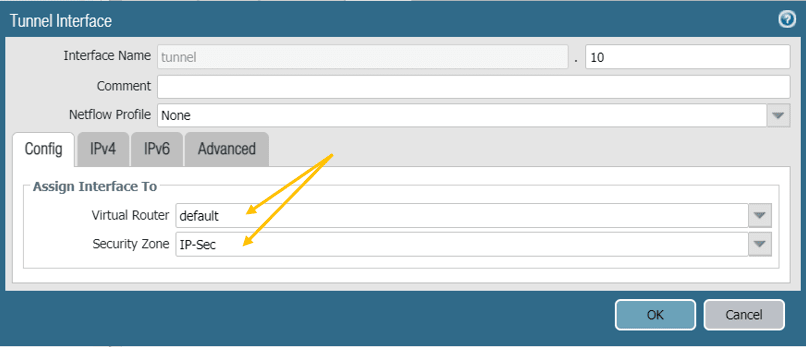
Let’s go ahead and create the Tunnel interface and connect the tunnel interface to the IPsec zone.
On the same Network Tab, click on Interfaces and click on Tunnel tab.
Click on the Add button to create a new Tunnel.
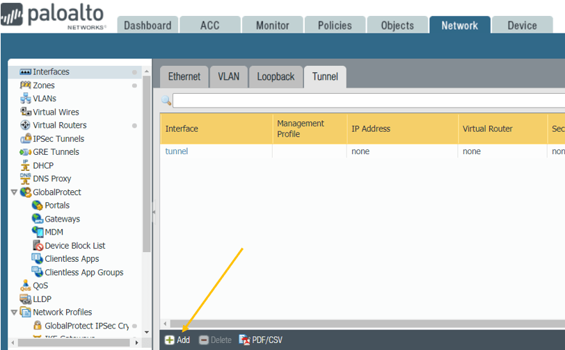
In the virtual Router, you can add your virtual Router and the zone which we have created. Follow the same steps on the firewall two as well.
Note: We are not going to configure any IP address under the IPv4 on the tunnel interface. If you plan to configure any dynamic routing over the IPsec tunnel, you might need to configure the IP address.
5. IPsec tunnel creation.
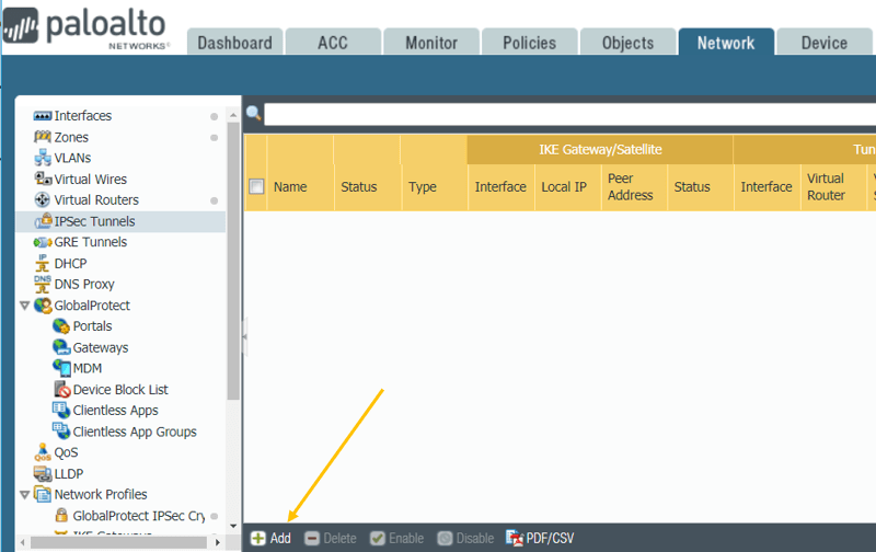
The final steps are to connect all the puzzles together. Click on Network and the left side, click on IPsec tunnels. Then click on Add.
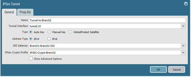
Name the Tunnel, for example, on the firewall one Tunnel-to-Branch2.
Tunnel Interface: Select the tunnel interface that we have created before.
Choose the IKE Gateway and the IPsec Crypto profile that we have created earlier and click on OK.
Note: You don’t have to add any proxy IDs as this is not a policy-based Tunnel, it is a route-based tunnel. Follow the same steps on the firewall 2.
As you can see the tunnel status is now shown as down.

The tunnel creation is complete, but do you think the remote end LAN side should be able to talk now?
Then the answer is NO!, because we have not configured the rules and routes for that.
6. Configure the Static routes for the IPSec tunnel.
On the Network, click on Virtual Routers and open your virtual Router.
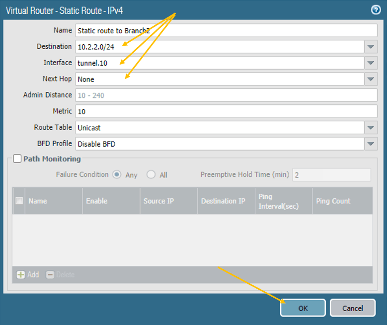
On the Static routes, define the static route on the first firewall that says “to reach 10.2.2.0/24 network goto the tunnel interface 10”
Similarly, on the Branch2 firewall, define the static routes “To reach the Network 10.1.1.0/24 goto the tunnel interface 10”
The next hop should be none.
7. Policy configuration.
The IPsec tunnel creation is now complete, but the Tunnel will not be active until any traffic is initiated. And for the initiated traffic from the Branch 1 LAN side to reach the Branch2 LAN side, we need to define a policy. Otherwise, it will be blocked by the firewall.
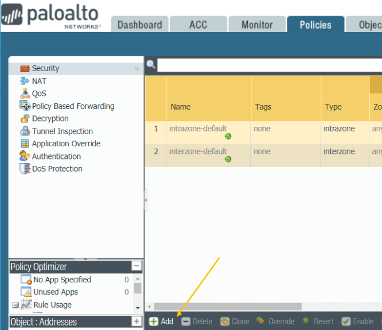
To create a policy, go to the Branch1 firewall and click on the Policies tab and click on Add.
Note: This policy configuration is the same for both Branch1 and two firewalls.
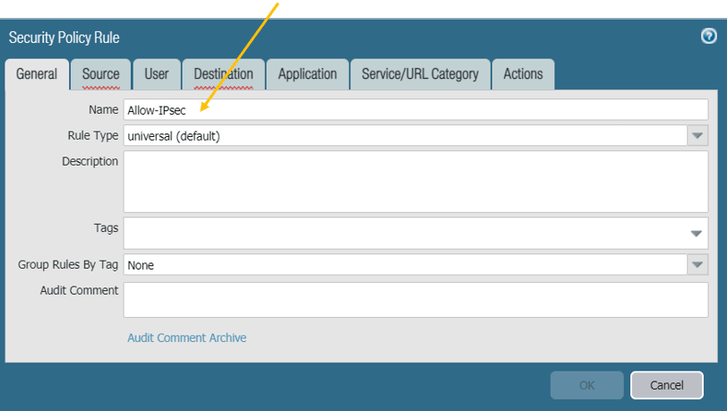
Under General give it a name: Allow-IPsec.
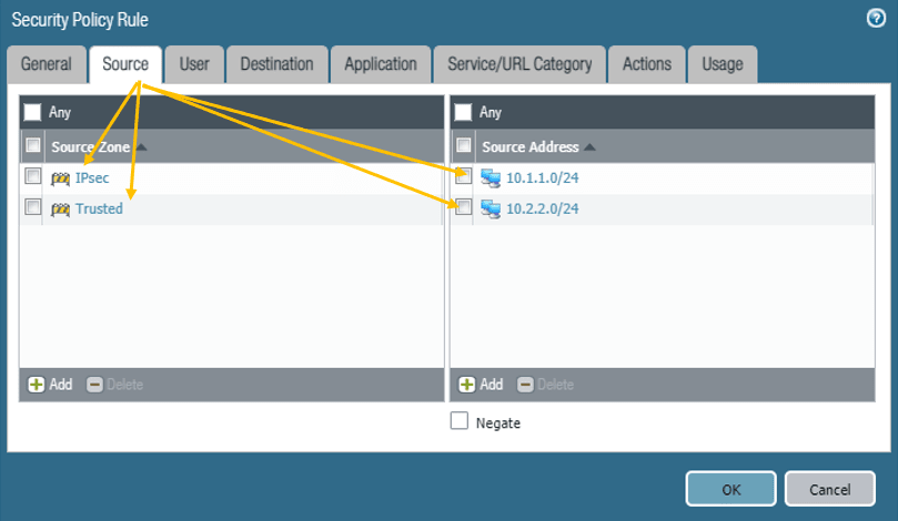
Click on the Source tab, and select the source zone as both IP-Sec and Trusted zone, and on the source subnet select Branch2 and Branch1 LAN subnets, which 10.1.1.0/24 and 10.2.2.0/24.
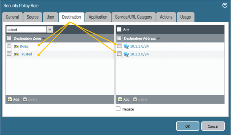
Click on the Destination, select the IP-Sec and Trusted zone, and Branch2 and Branch1 LAN address as the destination address.
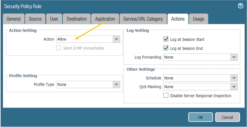
In the Action tab, make sure that you are Allowing the traffic, also check the boxes for the logs.
Once completed, you should be able to see policies on both firewalls like below.

8. Paloalto Firewall IPsec Verification.
We just completed the IPSec configuration. Let’s quickly check the tunnel status, as you can see, it is down at the moment.
Note: Red dot indicates it is down, and the Green indicates its up.

To bring the Tunnel up, either of the LAN sides has to initiate the traffic, let me go to Branch2 and start sending traffic towards Branch1.

As you can see I can ping Branch1 host from Branch 2 PC, let me check from Branch1 to Branch2, as you can see that worked just fine.

Let me check the tunnel status.
As expected, the IPsec tunnel turned Green now.

9. Final verification.
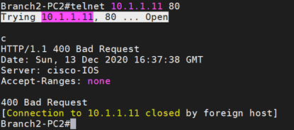
Let’s also verify the HTTP access between the sites.
I already enabled HTTP access on both the end hosts, to check the HTTP port is opened or not both sides, I can type the command telnet 10.1.1.11 80 from the Branch2 Router.
As you can see, I can talk over port 80 as well.
