

In some of the last blog I have covered how to create IPsec tunnels between different firewalls, however, those who want to learn more about the IPsec VPN should practice them on a Cisco router. In my opinion, if you can set up an IPsec tunnel on a Cisco router it would be a very easy task for other vendors.
configuring a site-to-site VPN using cisco ios is a little difficult for those who start as new.
First, everything is on a CLI and second, if you mess it up it will not work, so you need to start to troubleshoot the issue on the CLI and find out what’s going on. As always the best way to learn a technology is to practice and practice until you understand the concept on your head.
if you landed this page hoping to understand the IPSec configuration on a Cisco router, I would highly recommend you follow along. That way I can promise you that you will be able to understand it far better.
Why should I use IPsec Site-to-site VPN on Cisco routers?
The IPsec site to site VPN is mainly used to connect between different branch offices over the internet, the branch could be a small office to bigger ones, even a coffee shop or an ATM.
The main reason we use IPsec VPN is to provide a security mechanism on an insecure medium like the internet. By default IPv4 or IPv6 do not provide security. So if you use IPsec between the branch offices the data send between the sites will be encrypted. If you just start sending a packet over the internet without encrypting, some bad guy on the internet can sniff your data. So IPsec is the go-to solution by many enterprise users. Moreover, the internet is getting cheaper and cheaper, so why buy expensive dedicated link, rather we could use the same internet for the branch connectivity.
The only requirement for the IPsec tunnel setup is the internet and the supported hardware.
Can I set up IPsec VPN on cisco routers using gns3?
If you wanted to build a network lab some users prefer to have physical gear. The problem with that approach is that it is way too expensive. That’s why many users prefer to use virtualized solutions such as gns3 or eve-ng and even other hypervisors.
I am building this lab on GNS3, since gns3 supports many of the Cisco IOS router software you can easily spin up cisco routers on GNS3 and configure IPsec site to site VPN on Cisco IOS software on GNS3 itself. Some users use cisco CSR1000v routers on VMware ESXi or KVM hypervisors to do the lab, if you have that as an option that is also good, you can just follow along. In the end, you need to configure the topology like I shown below and everything should work just fine irrespective of the platform.
I am using a cisco vios router for this lab, any other cisco router would work just fine as well.
Building this IPsec lab is very easy, you just have to follow each step that I mentioned here and you should be good to go.
Read also,
How to Setup IPsec Tunnel between Paloalto and PFsense?
How To Configure Palo Alto Site To Site VPN Using IPsec?
How To Setup A Simple IPsec Site To Site Tunnel In Pfsense?
How To Configure IPsec VPN Between pfSense And Cisco Router?
Objective.
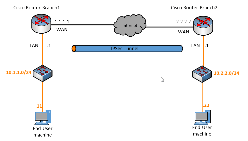
The objective for this lab is to build an IPsec tunnel between two cisco routers and allow communication between branch1 and 2 LAN subnets which are 10.1.1.0/24 and 10.2.2.0/24.
Steps to configure site-to-site VPN on cisco router.
- Setup the lab topology for IPsec configuration.
- Verify the LAN side connectivity.
- Phase 1 configuration on Branch1 router.
- Phase2 configuration.
- Apply it to the interface.
- Apply the same configuration on branch2.
- Verify the site-to-site communication.
1. Setup the lab topology for IPsec configuration.
Below is the topology that we are going to use, if you have followed my previous IPsec implementation blogs you can pretty much understand the topology, I just replaced other vendor equipment with two cisco routers.

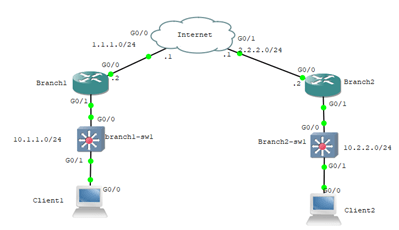
The lab that I am going to run is on GNS3, lets see how each component has been configured.
Configure the internet router.
For the internet router, I am using the Cisco router itself, since I am not using the real internet I would just use some random public IP addresses that we can remember easily, 1.1.1.0/24 towards branch1 and 2.2.2.0/24 towards branch2.
Below is the Ip configuration on the internet router, and you don’t have to configure anything else.
ISP#show ip int brief | ex un
Interface                  IP-Address      OK? Method Status                Protocol
GigabitEthernet0/0         1.1.1.2         YES NVRAM  up                    up
GigabitEthernet0/1         2.2.2.1         YES NVRAM  up                    up
ISP#
Configure the branch1 and 2 routers.
After you set up the internet router, let’s go ahead and configure the branch routers. So let’s start with branch1.
In branch1 the interface that is connected to the ISP is configured with the public IP address 1.1.1.1/24 and the LAN side is configured with 10.1.1.1/24, as you can see below.
Branch1#show ip int brief | ex un
Interface                  IP-Address      OK? Method Status                Protocol
GigabitEthernet0/0         1.1.1.1         YES NVRAM  up                    up
GigabitEthernet0/1         10.1.1.1        YES NVRAM  up                    up
Similarly, on the branch2 I have configured the internet-facing IP as 2.2.2.2/24 and the LAN side as 10.2.2.1/24
Branch2#sh ip int brief | ex un
Interface                  IP-Address      OK? Method Status                Protocol
GigabitEthernet0/0         2.2.2.2         YES NVRAM  up                    up
GigabitEthernet0/1         10.2.2.1        YES NVRAM  up                    up
For the internet routing to work, I have also added a default route towards the ISP from both branch1 and branch2 routers.
End-user machine configuration.
To simulate the end-user machine I am using the same cisco router and disabled the IP routing and configured the default gateway.
Below is the configuration on the branch1 end-user machine.
No ip routing
!
interface GigabitEthernet0/0
 ip address 10.1.1.10 255.255.255.0
!
ip default-gateway 10.1.1.1
And Branch2 end-user machine configuration.
No ip routing
!
interface GigabitEthernet0/0
 ip address 10.2.2.10 255.255.255.0
!
ip default-gateway 10.2.2.1
Check the internet connectivity.
If you have configured everything correctly you should be able to ping from Branch2 router public IP (2.2.2.2) from Branch1 router.
Branch1#ping 2.2.2.2
Type escape sequence to abort.
Sending 5, 100-byte ICMP Echos to 2.2.2.2, timeout is 2 seconds:
!!!!!
Success rate is 100 percent (5/5), round-trip min/avg/max = 3/4/5 ms
Branch1#
Branch2#ping 1.1.1.1
Type escape sequence to abort.
Sending 5, 100-byte ICMP Echos to 1.1.1.1, timeout is 2 seconds:
!!!!!
Success rate is 100 percent (5/5), round-trip min/avg/max = 2/3/4 ms
Branch2#
And here is the lab topology on the GNS3.

2. Verify the LAN side connectivity.
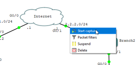
Before we proceed with the configuration, let’s see if we can reach the remote LAN side from both the branch client machines. Before we start the ping let’s do a packet capture on the wan side of the router as well.
To do a packet capture, right-click on the outside interface on the branch2 router connected to the internet router.

client2#ping 10.1.1.10
Type escape sequence to abort.
Sending 5, 100-byte ICMP Echos to 10.1.1.10, timeout is 2 seconds:
.....
Success rate is 0 percent (0/5)
client2#
of course, there was no response, lets check the Wireshark packet capture.
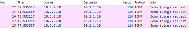
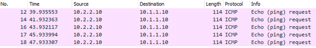
We can see the ICMP request but no reply. If you look into the diagram, we did a packet capture on the internet-facing link, how come I can see the private IP is going out to the internet side?
That’s because, on the branch edge router, we have configured the default route, so if the destination IP address doesn’t exist on the local LAN, irrespective of the IP address whether it public or private IP it would start sending it to the default route towards the internet.
Moreover, the internet service provider will not accept the private IP address range (RFC1918)
We are also not able to ping from site 1 to site 2.
client1#ping 10.2.2.10
Type escape sequence to abort.
Sending 5, 100-byte ICMP Echos to 10.2.2.10, timeout is 2 seconds:
.....
Success rate is 0 percent (0/5)
client1#
As you can see we are not able to communicate, let’s go ahead and start the IPsec configuration.
3. Phase 1 configuration on Branch1 router.
The IPsec configuration consists of two phases phase1 and phase2. Let’s go ahead and configure phase1 on the branch1 router.
Branch1(config)#crypto isakmp policy 5
Branch1(config-isakmp)#hash sha256
Branch1(config-isakmp)#authentication pre-share
Branch1(config-isakmp)#encryption aes 128
Branch1(config-isakmp)#group 2
Branch1(config-isakmp)#lifetime 28800
Branch1(config-isakmp)#exit
Configure the preshared key.
We have chosen pre-shared as the authentication method for phase 1 in our previous step, lets go ahead and configure the preshared key.
Branch1(config)#crypto isakmp key getlabsdone address 2.2.2.2
4. Phase2 configuration.
Next, we are going to configure the transform set in phase2 and the crypto parameters that we are going to use, which are esp-aes128 and esp-sha256-hmac.
Branch1(config)#crypto ipsec transform-set branch1set esp-aes 128 esp-sha256-hmac
Branch2(config)#exit
Configure the Access list.
We must now define the interesting traffic that is going to be sent through the tunnel. For that, we need to create an access list. In the access list, we are specifying what traffic to be encrypted. So here it should be the branch1 source subnet and the branch2 LAN destination subnet. When it comes to branch2 configuration it will be right opposite which you can see in the branch2 configuration.
Branch1(config)#access-list 100 permit ip 10.1.1.0 0.0.0.255 10.2.2.0 0.0.0.255
Configure the Crypto MAP.
We now need to configure the crypto map for the IPsec tunnel.
Branch1(config)#crypto map branch1map 5 ipsec-isakmp
% NOTE: This new crypto map will remain disabled until a peer
        and a valid access list have been configured.
We have entered into the crypto map configuration, you need to set the peer IP, which is the outside IP of the router and we are going to connect all the above configurations into the cryptomap so call the transform-set and the ACL that we defined earlier.
Branch1(config-crypto-map)#set peer 2.2.2.2
Branch1(config-crypto-map)#set transform-set branch1set
Branch1(config-crypto-map)#match address 100
Branch2(config-crypto-map)#set pfs group2
Branch1(config-crypto-map)#exit
5. Apply it to the interface.
We just completed the IPsec configuration, you need to configure this on the interface level.
Branch1(config)#int g0/0
Branch1(config-if)#crypto map branch1map
Branch1(config-if)#
*Feb 27 14:39:11.605: %CRYPTO-6-ISAKMP_ON_OFF: ISAKMP is ON
Branch1(config-if)#exit
6. Apply the same configuration on branch2.
When you apply the configuration on the remote side, you need to make sure whatever the IPsec parameters that you defined should match on the remote, except the peer IP and the ACL configuration, which will be the right opposite of the branch1 configuration.
Branch2#conf t
Enter configuration commands, one per line.  End with CNTL/Z.
Branch2(config)#crypto isakmp policy 5
Branch2(config-isakmp)#hash sha256
Branch2(config-isakmp)#authentication pre-share
Branch2(config-isakmp)#encryption aes 128
Branch2(config-isakmp)#group 2
Branch2(config-isakmp)#lifetime 28800
Branch2(config-isakmp)#exit
Branch2(config)#crypto isakmp key getlabsdone address 1.1.1.1
Branch2(config)#access-list 100 permit ip 10.2.2.0 0.0.0.255 10.1.1.0 0.0.0.255
Branch2(config)#crypto ipsec transform-set branch2set esp-aes 128 esp-sha256-hmac
Branch2(cfg-crypto-trans)#exit
Branch2(config)#crypto map branch2map 5 ipsec-isakmp
% NOTE: This new crypto map will remain disabled until a peer
        and a valid access list have been configured.
Branch2(config-crypto-map)#set peer 1.1.1.1
Branch2(config-crypto-map)#set transform-set branch2set
Branch2(config-crypto-map)#set pfs group2
Branch2(config-crypto-map)#match address 100
Branch2(config-crypto-map)#exit
Branch2(config)#int g0/0
Branch2(config-if)#crypto map branch2map
Branch2(config-if)#
*Mar  4 17:16:08.786: %CRYPTO-6-ISAKMP_ON_OFF: ISAKMP is ON
Branch2(config-if)#exit
Branch2(config)#exit
Branch2#
7. Verify the site-to-site communication.
We just completed the configuration on both the branch 1 and 2 sides and I should be able to communicate from both sites.
client1#ping 10.2.2.10
Type escape sequence to abort.
Sending 5, 100-byte ICMP Echos to 10.2.2.10, timeout is 2 seconds:
!!!!!
Success rate is 100 percent (5/5), round-trip min/avg/max = 4/4/6 ms
client1#
client2#ping 10.1.1.10
Type escape sequence to abort.
Sending 5, 100-byte ICMP Echos to 10.1.1.10, timeout is 2 seconds:
.!!!!
Success rate is 80 percent (4/5), round-trip min/avg/max = 3/4/8 ms
client2#
As you can see, we can ping the remote ends from both the end-user machines.
How to check IPsec tunnel status in the Cisco router?
You can type the command show crypto isakmp sa to see the phase1 of the tunnel status, if it is not established the output would be empty.
Branch1#show crypto isakmp sa
IPv4 Crypto ISAKMP SA
dst             src             state          conn-id status
2.2.2.2         1.1.1.1         QM_IDLE           1001 ACTIVE
IPv6 Crypto ISAKMP SA
Branch1#
Branch2#show crypto isakmp sa
IPv4 Crypto ISAKMP SA
dst             src             state          conn-id status
2.2.2.2         1.1.1.1         QM_IDLE           1001 ACTIVE
IPv6 Crypto ISAKMP SA
Branch2#
For phase2 you can type the command show crypto ipsec sa that will give you more details about the tunnel and how many packets are encapsulated over the tunnel.
Validate the IPsec traffic.
Remember when we did the ping test initially we were able to see the ICMP request came out from the router outside interface, lets see what we are going to see now.
I ran a continuous ping from site 2 client to site1 client.
client2#ping 10.1.1.10 rep 100
Type escape sequence to abort.
Sending 100, 100-byte ICMP Echos to 10.1.1.10, timeout is 2 seconds:
!!!!!!!!!!!!!!!!!!!!!!!!!!!!!!!!!!!!!!!!!!!!!!!!!!!!!!!!!!!!!!!!!!!!!!
!!!!!!!!!!!!!!!!!!!!!!!!!!!!!!
Success rate is 100 percent (100/100), round-trip min/avg/max = 3/7/17 ms
client2#
Let’s look at the Wireshark capture, what do you see?

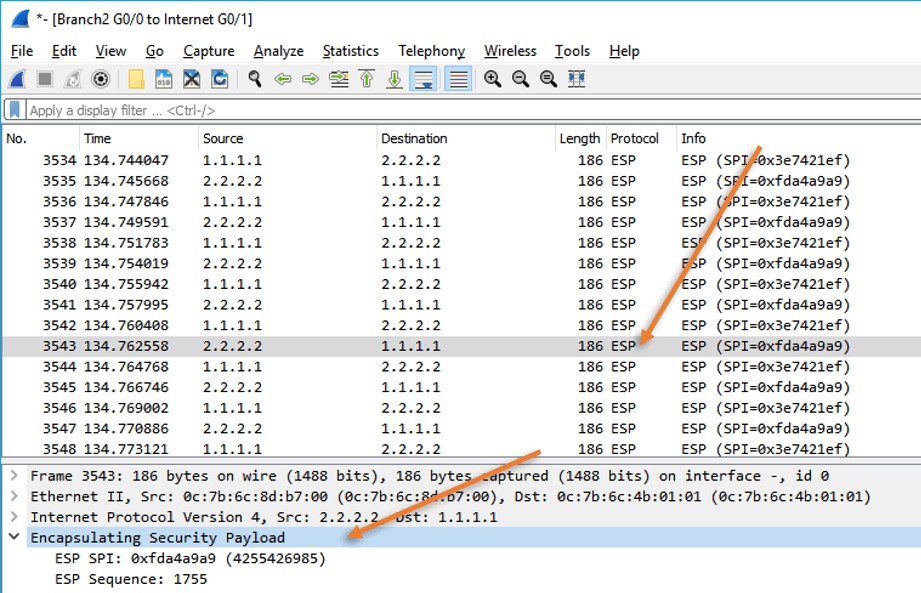
As you can see, we are no longer seeing the ICMP packet with private range, and the communication is only between the public IP addresses. However, did you notice the ESP protocol and payload? That’s because our ICMP packet is encrypted inside the ESP payload. So if someone were to do a packet capture on the internet they could see only the source and destination public IP address and they cannot see the payload data. That’s the reason IPsec is used over the internet to provide security between the branch offices.