In the last article, we looked at how to configure an IPsec tunnel on a FortiGate firewall using the IPsec wizard. This time, we’ll explore how to set up an IPsec tunnel in FortiGate manually, step by step.
You can create multiple IPsec VPN tunnels between sites. The traffic sent through the tunnel will be encrypted. If someone were to sniff the packets, they would see only the public source and destination IP addresses not the internal packet contents. Instead, it would appear as an ESP (Encapsulating Security Payload) packet.
We will be using the below topology to setup the Ipsec tunnel.
Before setting up the IPsec tunnel, we’ll first test connectivity between the end-user machines at each site. Initially, communication will fail. After configuring the IPsec tunnel, connectivity will be established.

Both end-user systems are Linux Ubuntu machines. While both machines can access the internet, they cannot communicate directly with each other across sites.
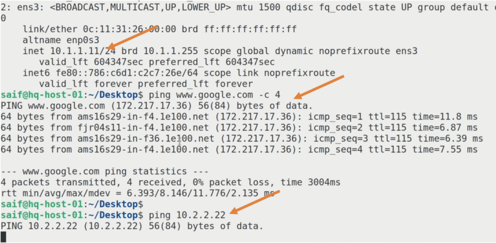
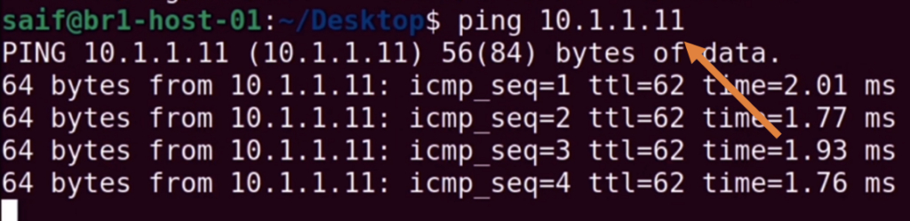
Let’s begin by logging into the HQ system. The terminal for the HQ system has a gray background.
Here’s what we observe:
- The HQ system has an IP address of 10.1.1.11.
- When I ping google.com, I receive a response, indicating internet connectivity.
- However, when I try to ping the remote branch’s end-user machine at 10.2.2.22, there is no response.
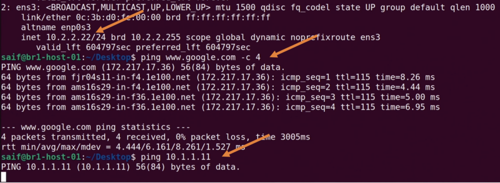
Similarly, at HQ, I can ping google.com but not the Branch1 end-user machine (10.2.2.22).
We will resolve this issue by setting up an IPsec tunnel between the two FortiGate firewalls.
Configure the IPsec tunnel at HQ FortiGate firewall.
The IPsec tunnel configuration consists of phase1 and phase2 configurations, we will fill in the phase1 details first and then will proceed to add the phase2 parameters.
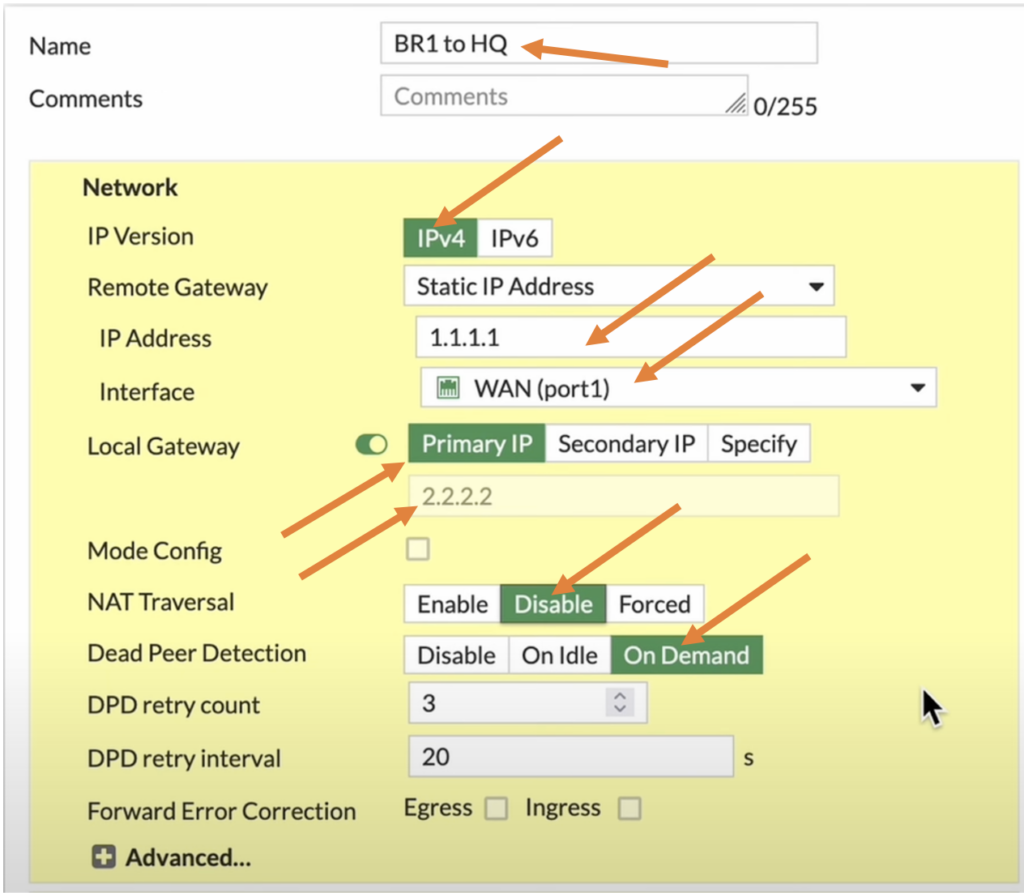
HQ Phase1 configuration.
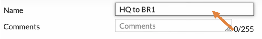
Name: Enter a name for the tunnel.
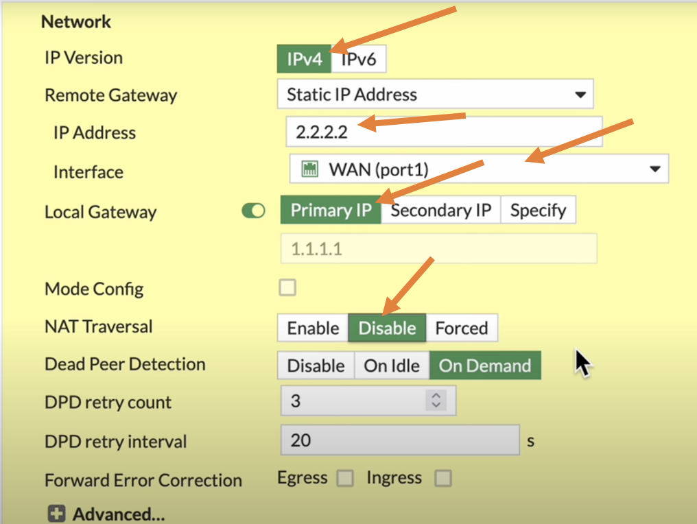
Network Settings:
- IP Version: IPv4
- Remote Gateway: Select Static IP Address.
- IP Address: Enter the public IP address of the Branch1 firewall. the initial phase1 tunnel is built on top of this public IP address.
- Interface: Select the WAN interface used to establish the tunnel.
- Local gateway: if you have single interface, it’s not mandatory to check this option as by default it will initiate the IPsec traffic from single wan interface that we selected, I am choosing this option anyway.
In case if you have secondary IP address on your WAN interface, you select that, and if you have third IP address, you can click on specify and specify the third IP address you have, which is not needed in our case.
- NAT Traversal: Disable if the firewall is connected directly to the public internet. Enable if the firewall is behind a NAT device (traffic will use port 4500 instead of 500).
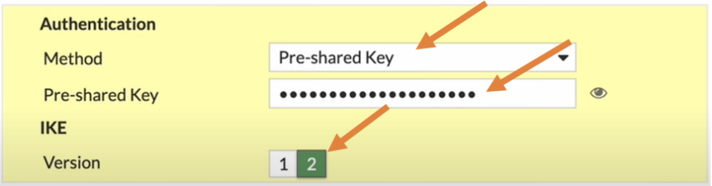
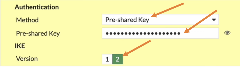
Now we have to define the authentication that we are going to use to authenticate the phase1 of the tunnel.
There are different methods available, but the most common one is the pre-shared key, and 90% of the deployments you will deal only with the pre-shared key.
Method: Choose pre-shared key from the drop down.
Pre-shared Key: Enter a strong pre-shared key, and copy the pre-shared key which will be required during the remote branch configuration.
When you are working with the 3rd party vendor, you must have to send this pre-shared key along with the IPsec parameter forms.
IKE version: enter the version as 2.
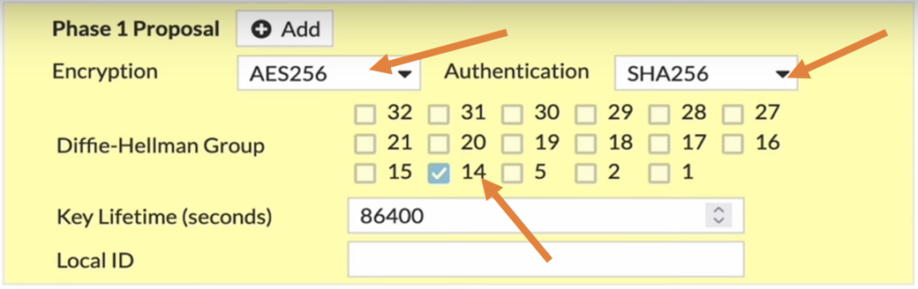
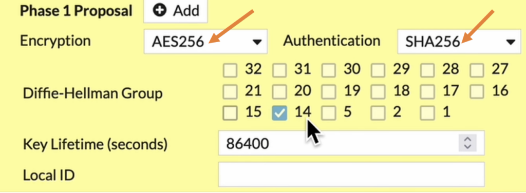
HQ Phase1 Proposal.
In the phase1 proposal, you will have to define the parameters that can be used for Encryption and authentication.
I have chosen AES256 as Encryption and SHA256 as authentication and for DH group, I will choose 14.
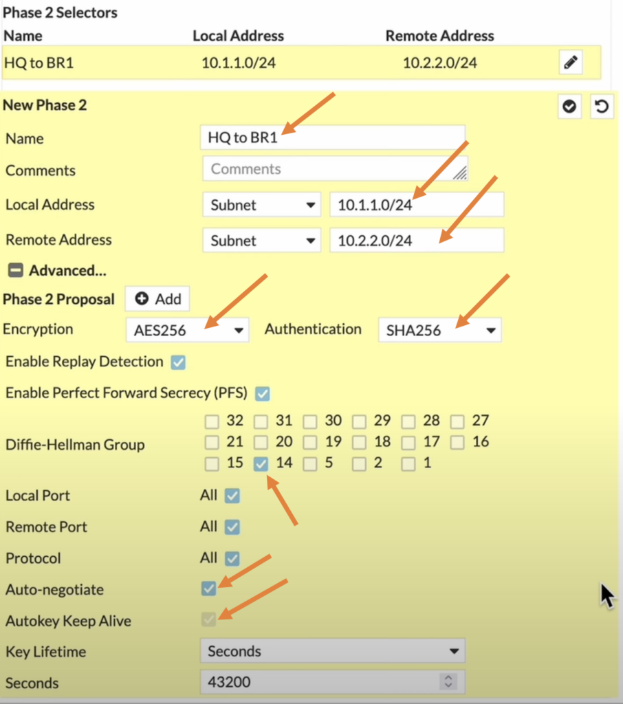
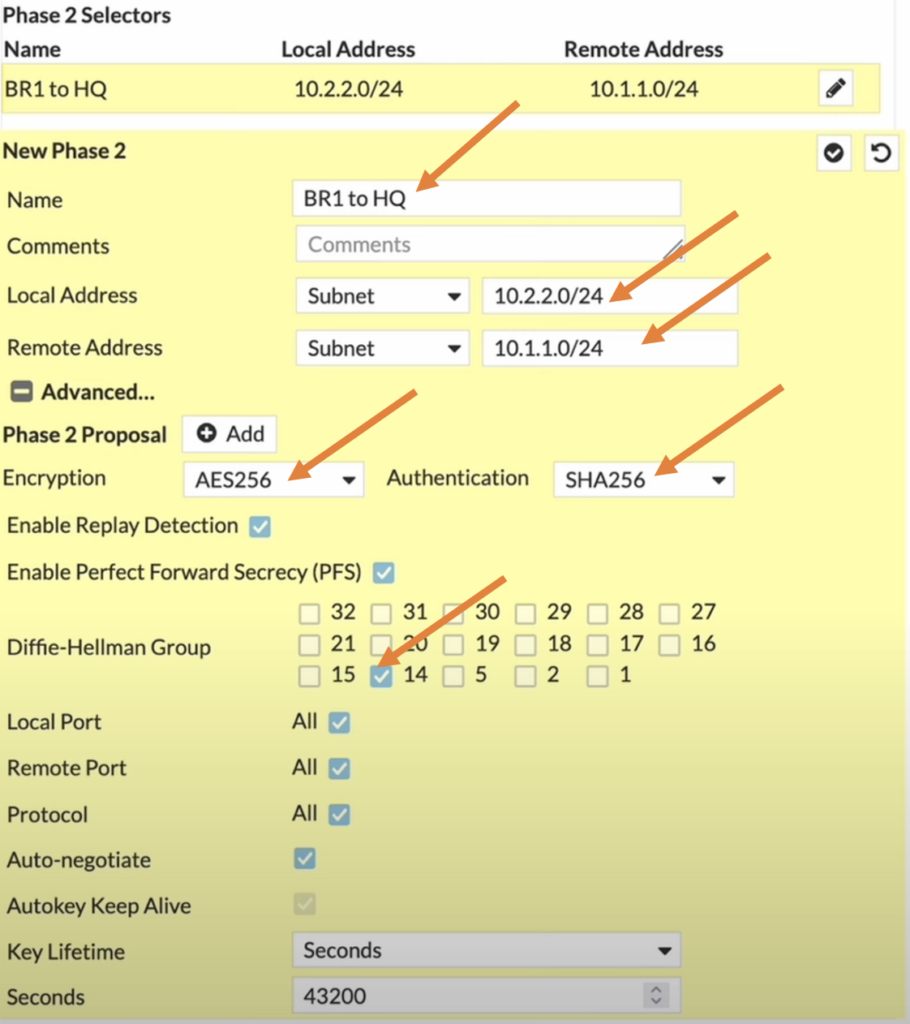
HQ Phase2 configuration.
We have completed the phase1 of the IPsec configuration, lets now proceed to configure the phase2 of the IPsec.
Name: Enter the name of your choice.
Local Subnet: Enter the HQ side address which is 10.1.1.0/24
Remote Address: Enter the remote branch address which is 10.2.2.0/24
HQ Phase2 Proposal.
Like we did in phase1 we have define the parameters on the phase2 as well, however these parameters doesn’t have to match with the phase1, but of course it needs to match on the phase2 of the remote side.
Encryption AES256, Authentication 256
DH group: 14.
If you want the phase2 of the tunnel to be up all the time, you can check the option that says auto negotiate and auto keep alive.
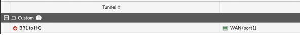
And click on the tick part at the top to add the phase2.
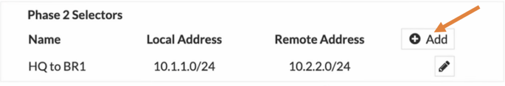
You can see the phase2 configurations added, and if you require to add more subnets you can click on the add button.
I have created a separate article that covers how you can configure IPsec tunnel on FortiGate firewall with multiple subnets. You may check out the article here.
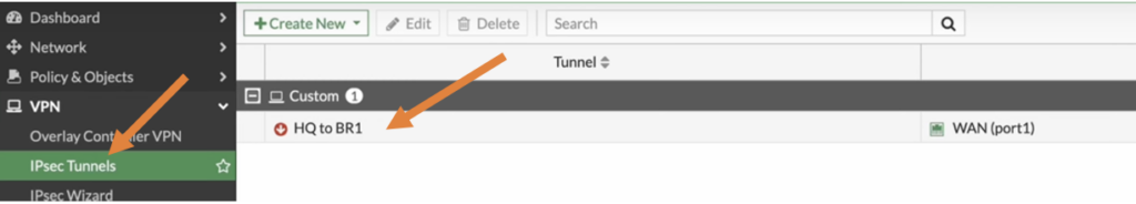
The tunnel is showing down, lets proceed to configure the policy so the HQ firewall will start the IPsec communication.
Configure the IPsec Policy at HQ.
In production networks, you will have policy in one direction with specific port number/services and of course depending on your requirement the policy changes.
Since this is a lab, I am going to allow traffic on both the directions.
So, I will be creating two policies that would allow the traffic from the HQ side to the branch1 outbound traffic, and also branch1 to the HQ side inbound traffic.
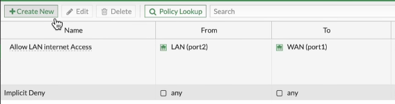
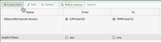
To configure the policy, go to Policy and objects.
Click on Create new to Create new policy for the IPsec.
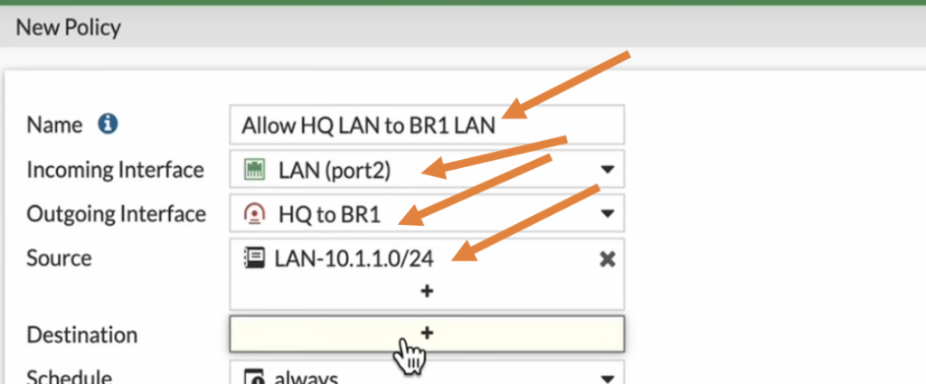
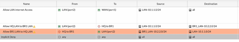
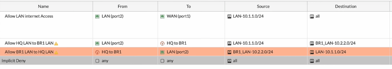
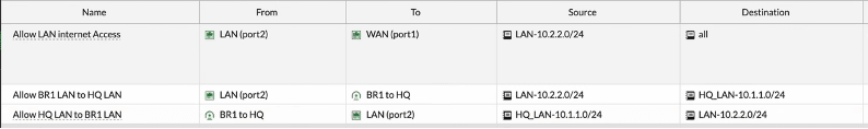
Configure HQ IPsec oubound policy.
Name: Enter the name for the policy.
Incoming interface: we are allowing the traffic from LAN to the IPsec so choose LAN here.
Outgoing interface: choose the destination interface which is IPsec.
Source: I already created LAN address object for my previous internet policy so I choose that.
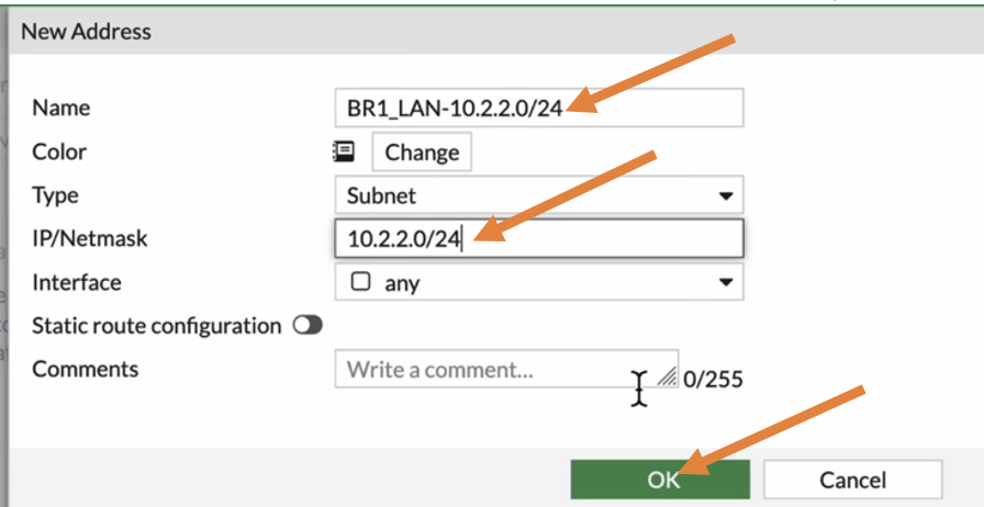
Destination: Here I need to define a subnet for the branch 1, so click on the plus Icon.
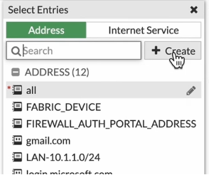
On the right panel, choose address and click on create.

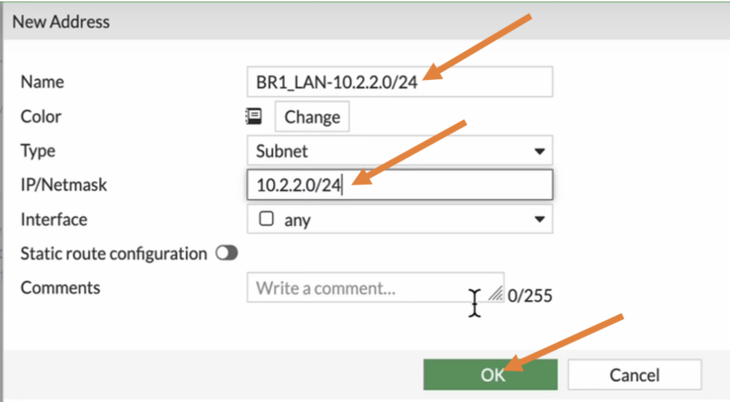
Enter the name and the address of Branch 1 and click on OK.
In the destination choose the address object that we just created.
Schedule: Always.
Service: All.
Action: Accept.
Uncheck the NAT option.
Log allowed traffic.
Check the option that says Enable this policy
And click on ok.
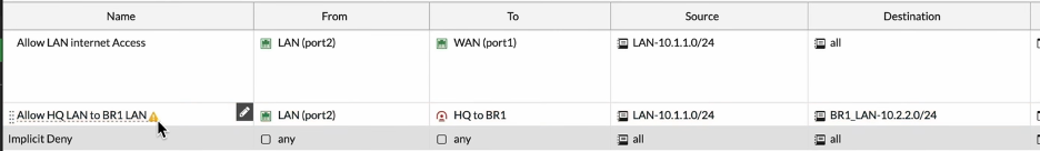
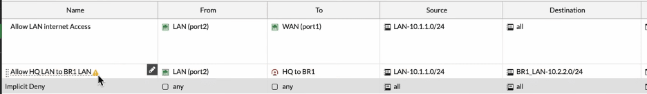
The traffic from LAN side to the IPsec is now enabled, you will see an exclamation mark next to the policy, that’s because the tunnel is down.
Lets enable from the other way around which is from Branch1 to the LAN side.
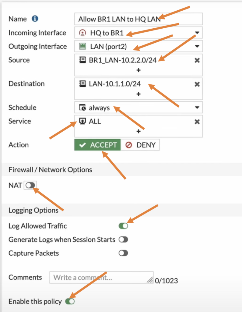
Configure HQ IPsec inbound Policy.
Click on create new on the Policy creation wizard
In the new policy configure as follows.
Name: Enter a user-friendly name.
Incoming interface: As we are allowing the traffic from the branch one, choose the IPsec tunnel that we just created.
Outgoing interface: choose the LAN interface.
Source: Select the branch1 subnet address object.
Destination: Choose the LAN address object.
Schedule: will be always.
Service is all.
Action: Accept.
Uncheck the NAT option.
And Log allowed traffic option.
Enable this policy and click on Ok.
We just now created policies for both directions.
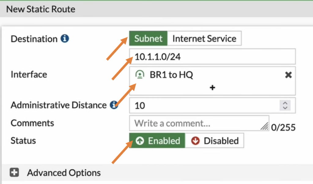
Configure the static route at HQ.
At this point when the IPsec tunnel comes up, the FortiGate firewall doesn’t know how to reach 10.2.2.0/24, so we need tell FortiGate to forward the traffic to the IPsec tunnel that we just created.
So we would require to create a route for that, you could use dynamic route or static route.
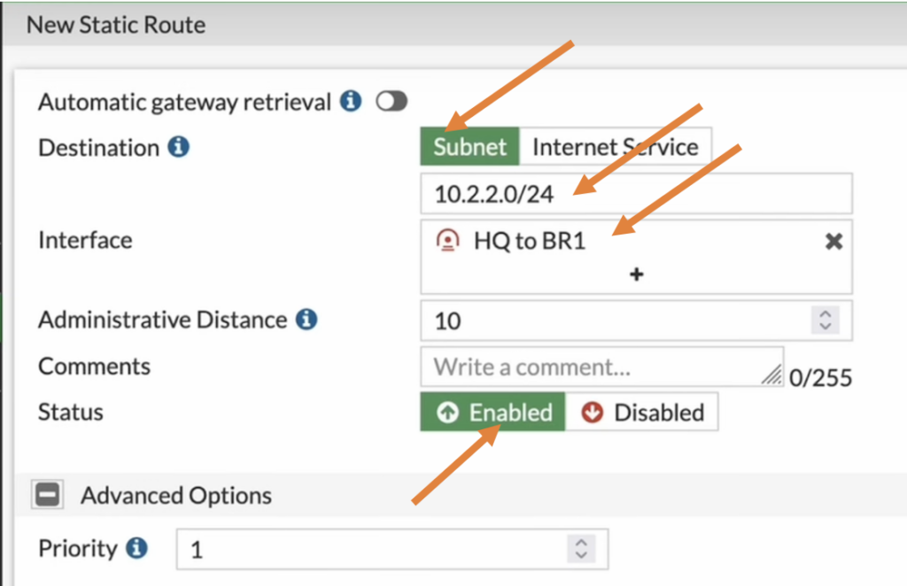
I am using static route for this purpose, so click on Network and static routes.
Here I am telling the router, if you want to speak with branch1 subnet 10.2.2.0/24, take the IPsec tunnel.
Click on Create new under static route screen.
Destination: Branch 1 address 10.2.2.0/24.
Interface: IPsec tunnel.
Don’t worry about the priority for the route, which can be manipulated when you have multiple tunnels.
Click on OK here.
We have configured the IPsec tunnel, its policies and routes on the FortiGate firewall at the HQ side.
Let’s now move on to the branch1 side of the configuration.
Configure the IPsec tunnel at Branch1 FortiGate firewall.
Like we did in the HQ, the branch1 configuration will also be the same except few changes.
So, let’s start with the IPsec configuration.
Branch1 Phase1 Configuration.
Name: Enter the name of the tunnel.
IP version: IPv4.
IP address: Enter the remote side WAN IP address.
Interface: the WAN IP address of the branch 1 where the HQ’s remote IP is configured.
Local Gateway: Enable it, and click on Primary IP, you will see the IP address 2.2.2.2 is reflected here.
NAT Traversal: Disable.
Phase1 authentication.
Method: Pre-shared key.
Pre-Shared key: Enter the pre-shared key that you copied at the HQ while creating the IPsec tunnel.
Choose 2 as IKE version.
Branch1 Phase1 Proposal.
Just like pre-shared key, the proposal as well should match on both side for the tunnel to be up.
In the encryption choose AES256 and Authentication choose SHA256.
Diffie-Hellman Group choose 14.
Branch1 Phase2 configuration.
In the Phase2 selectors configure as follows.
Name: Enter the name for the phase2.
Local Address: Subnet and choose the branch1 subnet which is 10.2.2.0/24.
Remote Address: Enter the HQ subnet which is 10.1.1.0/24.
Expand the Advanced,
And in the phase2 proposal choose AES256 and SHA256.
Diffie Hellman group choose 14.
Check auto negotiate and auto keep alive option checked, this will ensure the tunnel is always up even when there is no traffic.
And finally click on OK.
As you can see the tunnel is still down, although HQ side is initiating the tunnel, Branch1 not responding as there is no policy defined for it to start the IPsec negotiations.
let’s proceed to create the policy and the routes.

Branch1 IPsec policy configuration.
In the policy and objects.
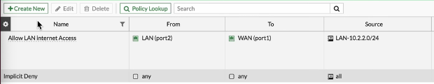
As you can see, I only have a single policy that allow the traffic towards the internet. Let me click on create new to create new policy for the IPsec tunnel in branch1.

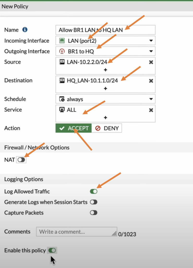
In the new policy.
Name: Enter the name of the policy.
Incoming interface: Choose the LAN as we are creating the outbound policy.
Outgoing interface: The IPsec tunnel that we just created.
Source: Branch1 LAN address.
Destination: HQ Address, just like we did in HQ, I didn’t have address object for HQ subnet so created and added to the destination side.
Service: All.
Action: Accept.
Uncheck the NAT option.
Check the log allowed traffic option.
Check Enable this policy option.
And then click on Ok.
Branch1 IPsec inbound policy.
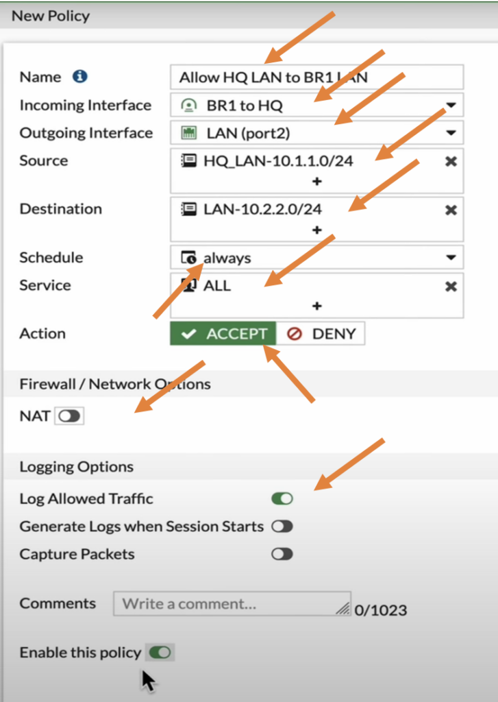
Let’s now create another policy that would allow the traffic coming from the remote branch.
Name: Enter the name for the policy.
Incoming interface: Choose the IPsec tunnel.
Outgoing interface: Choose the LAN interface.
Source: Select the remote HQ LAN subnet.
Destination: Choose the Branch1 LAN subnet.
Service: All.
Action: Accept.
Uncheck NAT.
Check the Log allowed traffic.
Check the Enable this policy option.
And then click on Ok.
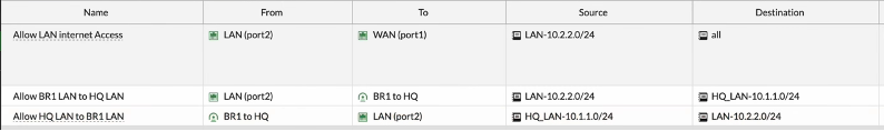
Note: Did you notice, that the IPsec tunnel turned green which indicates the tunnel came up as soon as we enabled the policy at the branch1.
Both the inbound and outbound policy at the branch1 is now complete.
Configure the IPsec route for Branch1.
If you start a traffic for example, ICMP ping, the traffic will reach to the branch1 however return traffic that is destined to 10.1.1.0/24 doesn’t know how to get to HQ, so it will take the default route and start sending it to internet. So basically the traffic will never reach to the HQ.
So we need to tell the branch1 firewall to send the traffic destined to 10.1.1.0/24 to take the IPsec path.
Like we crated the static route for HQ we will also create a route for branch1 as well.
Goto network-> static routes.
Create new.
In the Destination Subnet Enter the HQ subnet which is 10.1.1.0/24.
Interface: this will be the IPsec tunnel.
And click on OK.
Test the IPsec connectivity.
In the beginning of this lab, we initiated the ping traffic from the HQ side to the branch 1, so it was not working at that time, so let’s verify that again.
In FortiGate firewall, You can now go to dashboard -> network-> Click on the IPsec widget, and you will see the traffic passing through the tunnel (Incoming data and outgoing data.)
And both the phase1 and phase2 are up.


On the HQ side, you can see the ping started to work, and I stoped and restarted the ping test and it was successful. b. v
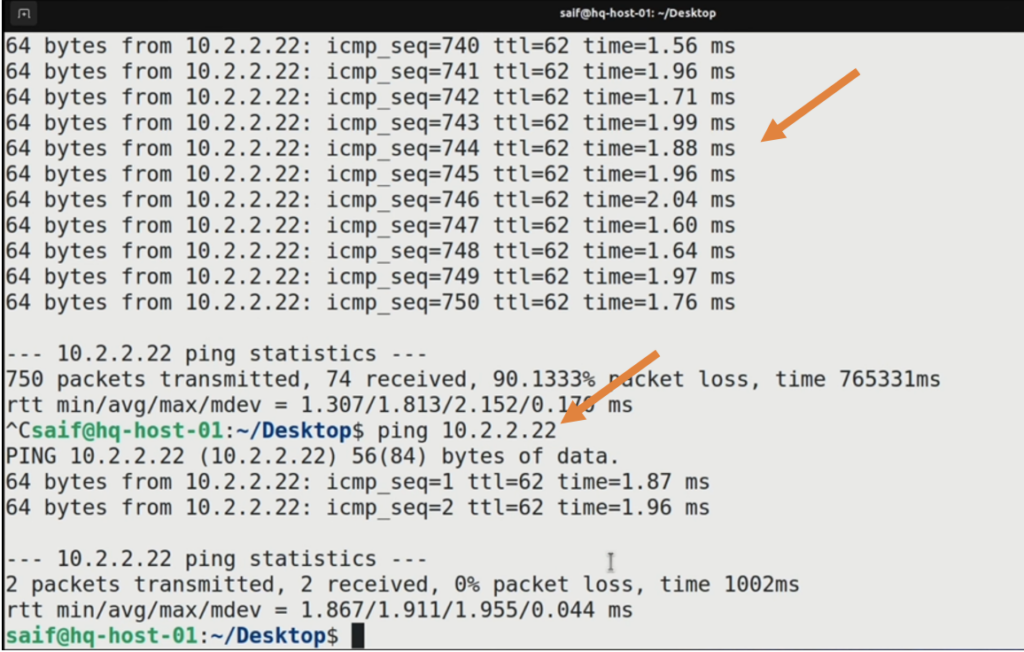
However branch1 didn’t resume like it did in HQ, let me stop the ping and start again.
Its now worked this time.
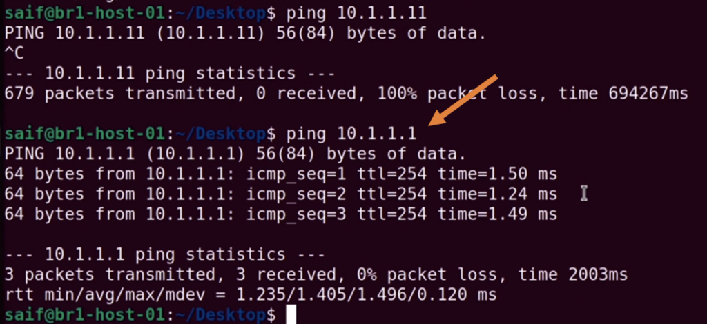
We were pinging the HQ firewall, let also try to ping HQ PC 10.1.1.11
And that worked fine as well.
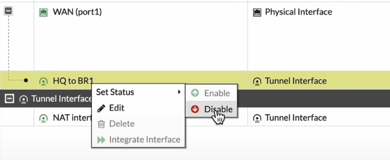
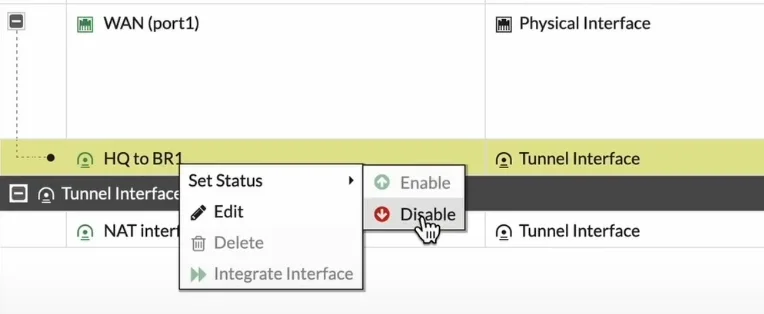
How to bring down the IPsec tunnel in FortiGate?.
Goto network -> Interfaces.
Choose the WAN interface where the ISP is connected, right click on the tunnel and click on Disable.
To bring the tunnel back you can choose enable option.