
You’ve got a brand new MikroTik router and now you’re wondering how to set up IPsec between your headquarter’s FortiGate firewall and this new MikroTik router.
For those of you new to MikroTik, it might feel somewhat overwhelming to understand its functionality, especially when you’re trying to configure the IPsec site-to-site VPN between the FortiGate firewall and the MikroTik router for the first time. But don’t worry, we are going to do exactly that.
If you are new to mikrotik, you can get started with initial setup wizard automatically, which I mentioned here. If you prefer to configure MikroTik manually instead, then I have covered that as well here.
In the last blog article, we have looked at how you can setup IPsec site to site VPN between two mikrotik site locations.
In this blog article, we are going to build an IPsec site to site VPN between the FortiGate firewall and a Mikrotik router.
Below is the topology that we are going to build, the only thing that is working at each site is the connectivity towards the internet, and each site cannot communicate with each other.
At the end of the blog article you will have a working site to site VPN which allows communications from each side.

Let’s start with the FortiGate configuration and then we will move on to the MikroTik side of the configuration.
In case if you prefer to watch video, Here is the step by step instruction video.
step by step instruction video
Step by step to configure IPsec site to site vpn between FortiGate and MikroTik.
Configure the phase1 of the tunnel.
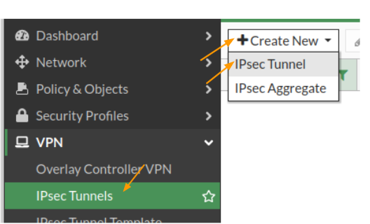
Login to the FortiGate firewall and then click on VPN-> IPsec tunnels -> create new -> IPsec tunnel.

In the IPsec configuration.
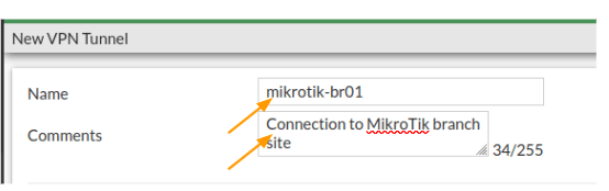
Name: Enter the name of the tunnel.
Comments: Though it is not mandatory, provide descriptive comments, as it would help you to identify each tunnel, as in when you add more tunnels.
Note: If you have got IPsec wizard, then you may enter the name and click on Custom and click on Next.

Configure the remote gateway.
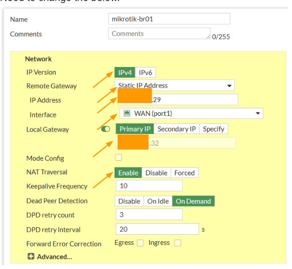
Network.
IP version: choose ipv4.
Remote Gateway: Static IP address.
IP address: enter the MikroTik public ip address
Interface: choose your outside interface.
Local Gateway : Primary public IP
If you have secondary or tertiary IP that you are using in the interface, you may choose that well, by selecting either Secondary IP or Specify. In my case it is only single IP so just choosing the primary IP here.
Nat Traversal: As we are not using the FortiGate firewall behind a NAT device, we can choose Disable here. In case if your firewall is behind a nat device, then you need to choose Enable here.
Need to change the below.

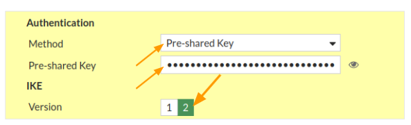
Authentication
Method: Choose Pre-shared key from the drop down.
Pre-Shared key: Enter a strong pre-shared key here.
IKE: Choose version 2.
I have seen people are choosing IKEv1 as the Isakamp version, thinking that FortiGate and MikroTik doesnt peer using the IKE2, however thats not the case, IKEv2, very well support with both FortiGate and the MikroTik.

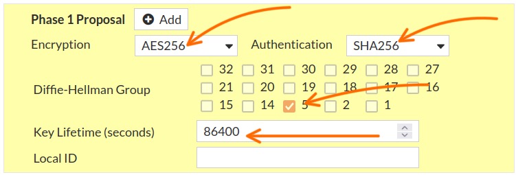
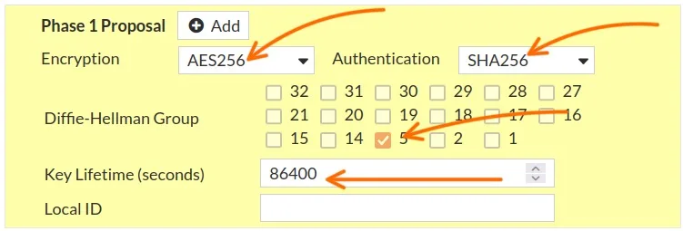
Phase1 proposal.
By default, you will see FortiGate selected multiple parameters are selected, however we dont want to do that, instead we want to choose what we defined.
Encryption: AES256
Authentication: SHA256
Remove everything else.
Diffie-Hellman Group: Choose 5.
Key Lifetime: leave the default to 86400
FortiGate phase2 configuration.
We have completed the phase1 configuration of the FortiGate side, lets now proceed with the FortiGate phase2 tunnel.
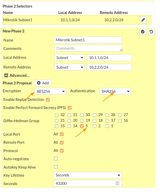
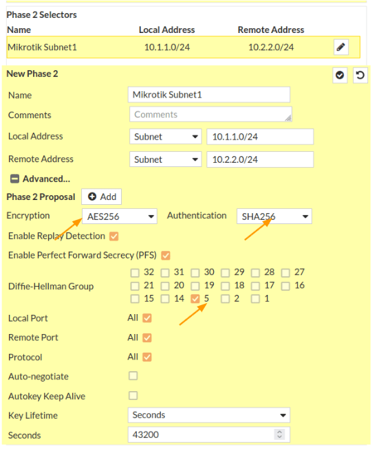
Scroll down to the Phase2 selectors.
Name: MikroTik Subnet1
Local Address: Choose subnet from the drop down. And the address will be 10.1.1.0/24
Remote Address: Subnet and the address will be 10.2.2.0/24
Click on Advanced.
You will all the phase2 parameters are selected, we need to remove all and specify our parameters.
For forigate VM appliances, you will not have any encryption or the authentication parameters selected, so you will have to define them as below.
Encryption: AES256
Authentication: Sha256
Diffi–Hellman Group: Choose 5.
Leave everything else default and click on Ok.
You could got to Dashboard -> Status -> IPsec dashboard to see the status of the IPsec tunnels.
You will see the new tunnel is now created and both the phase1 and phase2 is down at the moment.

Configure the route.
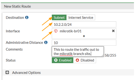
In FortiGate we just setup the tunnel, but for any traffic that are destined for 10.2.2.0/24, we need to direct them to goto the tunnel that we just created. For that we need to use routing. If you dont define the route, it will take the default route and try to go out to the internet, though it is a private IP.
Click on network-> Static routes -> Create New
Destination: Subnet
Enter the subnet 10.2.2.0/24 down below.
Interface: Choose the tunnel interface that we just set up and click on Ok.

Setup Policies for the tunnel.
We routed the traffic, however Firewall will by default block any traffic that is passing through the tunnel. So we need to open the door for the traffic to go through the tunnel.
Even if you configure everything on both sides for IPsec, except the security policies the tunnel will not come up. So creating a security policy for the site to site traffic is very curcial.
So to allow the traffic, we need to use something called security policies.
Goto Policy&Objects -> Firewall Policy -> Click on Create New.
This will open up the window to create new policy.
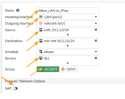
Name: Enter the name of the policy.
Incoming interface: This will be the interface from which the traffic is initiated. In our case, we are going to create a policy for the traffic that is coming from the LAN to the IPsec. So the interface will be LAN.
Source: 10.1.1.0/24 – I have created address object called LAN_10.1.1.0/24 with the 10.1.1.0/24 subnet.
Destination: 10.2.2.0/24 – Similarly, i have setup a address group called mkt-rmt-10.2.2.0/24 with the subnet ofcourse 10.2.2.0/24
Service: all.
Note: In production, we may not need to allow all the traffic, it again depends on the requirement, for your own branch sites, you will allow all, if it is some third party VPN, you will have to get it clarified about the traffic that is going to be allowed.
NAT: Disable the nat option.
Action: Accept.
Logging Options:
Log Allowed traffic: Selected and choose All Sessions.
Check the box, enable this policy and click on Ok.

We have allowed the traffic going from the headquarters to the MikroTik branch site, however we are not accepting any traffic coming from the MikroTik branch, let’s allow that.
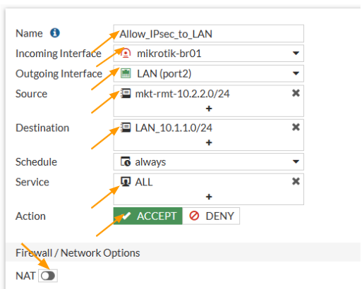
Configure the policy for return traffic.
In the same policy screen, click on create new
Name: Enter the name of the policy.
Incoming interface: This time the interface will be opposite, so select IPsec tunnel this time.
Outgoing interface: Choose LAN here.
Source: Enter the MikroTik subnet here, which is 10.2.2.0/24 – I called the previously created address group.
Destination: Enter our local subnet which is 10.1.1.0/24 – Previously added security group here as well.
Service: All.
Action: Accept.
Uncheck the NAT option.

Scroll all the way down.
Check the Log Allowed traffic option and select All sessions.
And click on Ok.
Thats the all configuration that is required at the FortiGate side, we have configured the IPsec tunnel, routes and the policies, and at the moment the tunnel will be down. ONly when we configure tunnel on the remote side the tunnel will come up, so lets get into the MikroTik side now.
MikroTik Phase1 configuration.
There are multiple ways you can get into the MikroTik router management GUI, however I recommend that you use winbox to access the MikroTik router.
Once you have the access, lets now go ahead and proceed with the IPsec configuration.
In winbox, click on IP-> IPsec
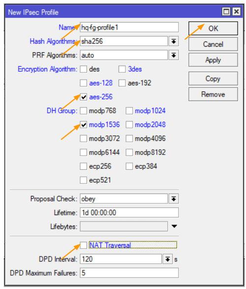
The phase1 of the MikroTik configuration starts with the profile, click on the profiles tab in the new IPsec window.
Click on the plus icon to add new profile.
Name: enter the name of the tunnel.
Has Algorithms: This should match with the one that we configured on the remote end which is sha256.
Encryption Algorithm: aes-256
DH Group: modp 1536 – which represents the dh group 5.
NAT traversal: As we have already connected the MikroTik directly to the internet, we can uncheck the option that says NAT Traversal and then click on Ok.

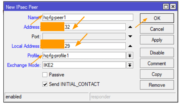
Configure the MikroTik IPsec peer.
Click on the peers tab, and press the plus icon to add new peer.
Name: Enter the name of the peer.
Address: Enter the public IP address of the FortiGate firewall here.
Check the box that says Send initial_contact and click on Ok
Local address: enter the local address of the MikroTik router.
Profile: choose the profile that we defined and click on ok.

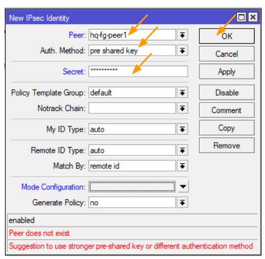
Configure the pre-shared key.
Recall when I requested you to write down the pre-shared key that we configured on the FortiGate side? We’ll need to utilise this exact key for the phase1 configuration of our IPsec site-to-site tunnel.
Navigate to the Identities tab and hit the plus icon to add a new Identity.
For ‘Peer,’ select the HQ FortiGate peer we previously identified.
Under ‘Auth Method,’ choose ‘pre-shared-key.’
For ‘Secret,’ input the same pre-shared key we defined earlier on the FortiGate firewall.
Then, click on ‘OK.’
Don’t fret about the peer not existing; we’re going to establish it soon enough.

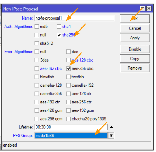
Configure the MikroTik Phase2 proposal.
You may now click on the proposal tab, and click on the plus icon to add.
This configuration again should match with the FortiGate side.
Name: enter the proposal name.
Auth. Algorithms: sha256
Encr. Algorithms: aes-256-cbc
Pfs group: modp 1536 which represents the dh group 5.

Configure the policies.
This is where you define the subnets that you are going to send across the tunnel to communicate with each end. It is important that both side should match, if the subnet doesn’t match the phase2 will not come up.
If you want to add multiple subnets, you can continue to add more subnets here.
Click on the policies tab, and click on the plus icon to add new policies.
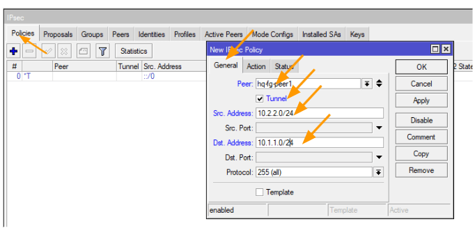
A New IPsec policy window will now open up.
General:
Peer: Select the peer from the drop down.
Tunnel: Check the box.
Src.Address: 10.2.2.0/24
Dst.Address: 10.1.1.0/24
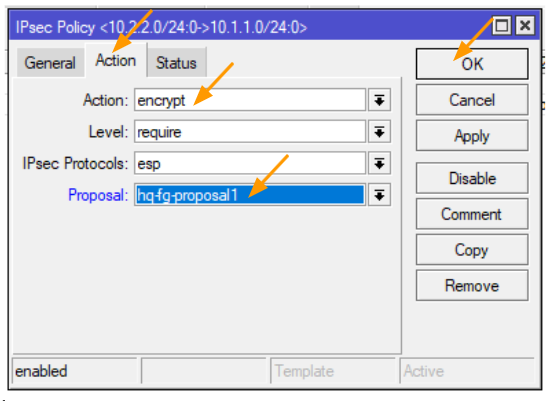
And click on the Action tab.

In the action tab, choose encrypt.
Proposal: select the phase2 proposal that we defined and then click on Ok.

Accept the traffic at MikroTik firewall.
By default, any traffic that is going out of the MikroTik firewall will be nated because of the default nat policy, we want to define a policy on top of the exsinng policies to accept the traffic that is initiated from MikroTik LAN side to the FortiGate remote end.
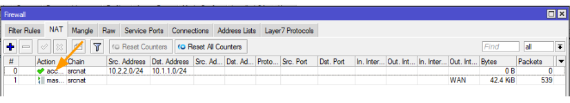
CLick on Firewall-> NAT.
Click on the plus icon to add new nat policies.
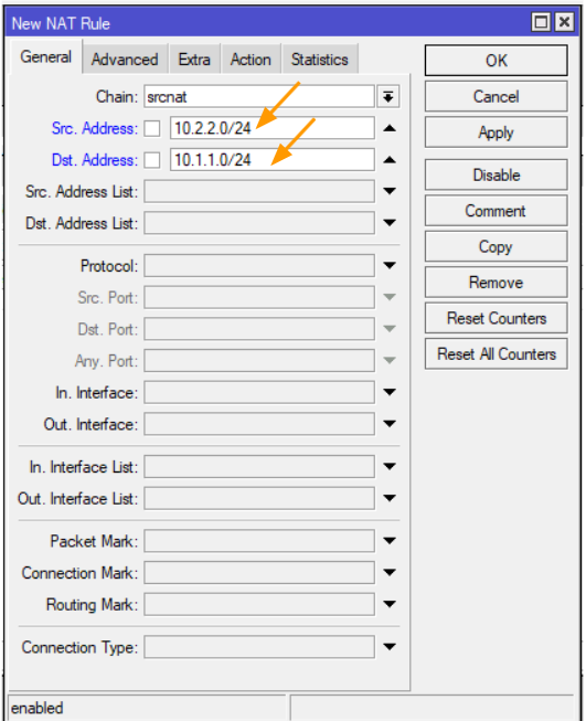
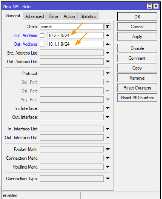
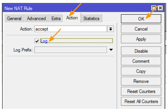
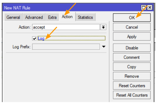
In the new Nat rule window.
Src.Address: 10.2.2.0/24
Dst.Address: 10.1.1.0/24
Click on the Action tab.
In the Action drop down choose accept, and log the traffic and click on Ok.
By default, you will see the rule underneath the default nat rule, we need to move the newly created rule to the top.
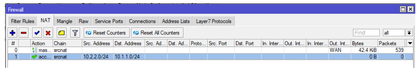
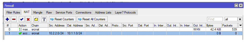
Drag the newly created rule to the top.

Test the IPsec connectivity.
We have configured everything, let’s now go ahead and test the IPsec connectivity.
First we will test the phase1 of the tunnels on both the MikroTik and FortiGate, and secondly, we will check the phas2, and finally we will test the connectivity from both the sides using an end user machine.
Verify the phase1 and phase2 connectivity in MikroTik.
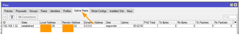
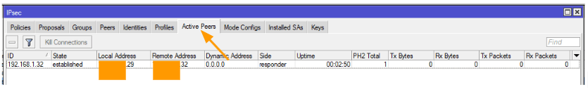
Verify Phase1 on the MikroTik.
To check the phase1 connectivity in MikroTik you can click on IP-> IPsec->Active peers.
As you can see, the state that says established, you could also see the PH2 total is 1, which means we have a phase2 active as well, lets look at that.
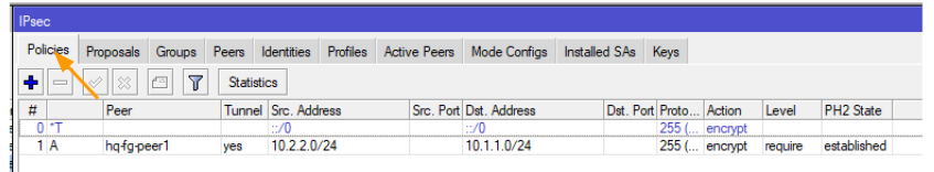
Verify Phase2 on the MikroTik.
Click on the Policies tab, and then lookout for the policies that we defined for this tunnle.
Here you can see on the extreme right, PH2 state is established.

Verify the phase1 and Phase2 of the FortiGate firewall.
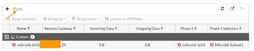
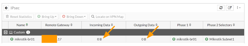
In FortiGate, goto Dashboard-> Status-> IPsec tunnels, here you can see both the phase1 and the Phase1 is showing up (the green up arrow indicates it is up)
Note: you will have to manually add the IPsec widget to the status Dashboard if you have not already done so.
Both the incoming and outgoing data is currently empty, as we have not initiated any traffic.

Test the remote end connectivity.
We know the IPsec site to site VPN is up, however we need to initiate some traffic to see if it is really working or not.
Test the connectivity from the Mikrotik LAN side.
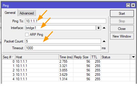
To test the connectivity from the MikroTik side, you could goto MikroTik-> Tools-> Ping
Ping to: 10.1.1.1 (FortiGate LAN IP)
Interface: bridge1
Packet count: 5
And click on Start, if you have done everything correctly you will get an ICMP response, else you will get a timeout.
In our case, we are getting the ICMP response which means the tunnel is up and we are good to go.

Test the connectivity from the FortiGate LAN side.
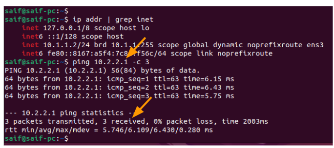
The same way, we can test from the FortiGate LAN side by logging into any of the PC’s that are connected to the FortiGate LAN side.
I just logged into one of the FortiGate LAN machine, as you can see it has got an Ip address 10.1.1.2
Let me try to ping the MikroTik LAN side, as you can see, that I am able to communicate with the remote branch, which is awesome.

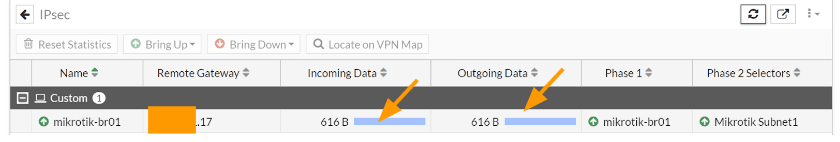
You can now reload the IPsec tunnel status in FortiGate and as you can see the incoming and outgoing Data now increased from 0Bytes.

nik
Tuesday 11th of November 2025
Thank you so much! the only article that made IPsec work for me - however, I want to note that there are no routing settings on the part of Mikrotik, and I have no traffic.
Masudur Rahman
Wednesday 24th of September 2025
Thanks a lot for the comprehensive guideline, it's helped me a lot. Appreciated
Khurram Shahzad
Tuesday 26th of August 2025
Hello Brother how are you? I have configured as you did and my both interfaces are up, but i am not able to communicate with each other clients. no Ping work to other site. but connections are green and up
Jhonatan
Friday 19th of July 2024
helo my friend,
help-me please.
how to configure default router 0.0.0./0 from mikrotik over ipsec tunel ?
Claus
Thursday 16th of May 2024
Dear Saifudheen,
thank you for your great work.
We only have one problem here: our Mikrotik is an LTE gateway, and our provider is unfortunately unable (despite repeated requests) to give us a static IP without a CG firewall, so we only have the option of a DialUP tunnel.
Is this also possible or have you ever made this work?
Instructions on this would certainly be helpful for many with a similar problem.
Many thanks in advance!