
When you want to connect two remote sites, the easiest and cheapest way is to deploy an IPsec tunnel. The only requirement to connect both offices is that you need a device that supports IPsec capability and an internet connection. That’s it, and you can now build an IPsec tunnel successfully between two sites.
ASA is one of the commercial firewall offerings from cisco used by many enterprise networks. Though it lacks some of the available features in the next-generation firewall, it still holds a market share. Pfsense, on the other hand, is an open-source alternate firewall from netgate. You have a free version of pfsense called pfSence CE (Community Edition) and pfsense plus, available only in pfsense hardware and on the cloud.
Unlike ASA, you can have your free version of pfsense deployed in your home network and deploy an IPsec tunnel from your home network to the ASA firewall at the office. Just because the pfsense is an open-source firewall, it doesn’t mean it is not as good as the ASA. I have personally migrated one of the labs running in ASA to Pfsense. The pfSense firewall is used by many enterprise networks and the cloud these days.
In this blog, we will build an IPsec site-to-site VPN tunnel between pfsense and the Cisco ASA firewall. After the tunnel is built, we will test the connectivity from both sides.
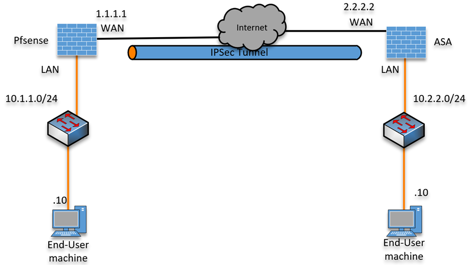
Below is the topology that we are going to work on.
We have a Pfsense firewall configured on the left connected to the internet; similarly, we have an ASA firewall connected on the right.
After the IPsec tunnel is built, we will initiate traffic from both sides to verify the connectivity.

Read also,
How to Configure IPsec Site to Site VPN Between Cisco ASA?
How to Set Up IPsec Site-to-Site VPN between FortiGate and ASA?
How to Configure IPsec Site to Site VPN Between PfSense and ASA?
How to Deploy Cisco ASAv in AWS? | Step by Step Guide.
Configure the IPsec Site to Site VPN on the pfsense firewall.
IPsec tunnel consists of two phases, phase1, and phas2.
Phase1 encrypts the link between two WAN public IPs. And phase2 is where actual encryption happens on the data traffic.
We will configure the phase1 parameters first and then configure phase 2.
And for the IKE version, we will configure it with IKEv2.
Phase 1 configuration on pfsense.
Login to the pfsense firewall.
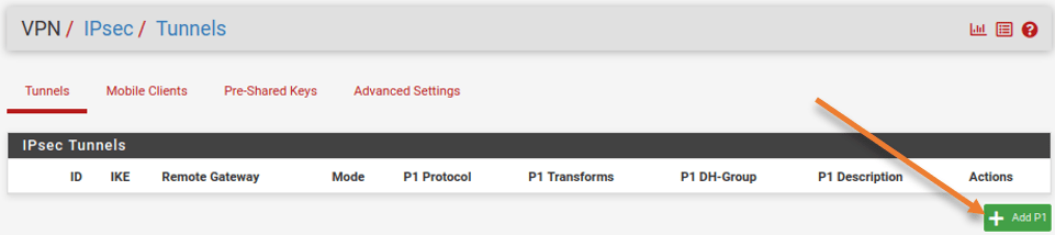
Goto VPN-> IPsec-> Tunnels.
Click on Add P1.

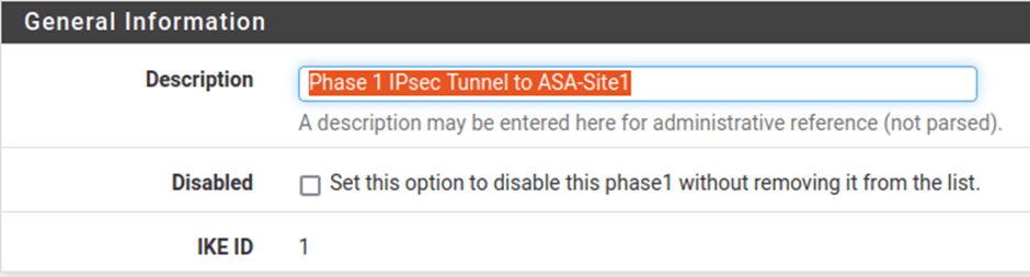
General information :
Description: Phase 1 IPsec Tunnel to ASA-Site1

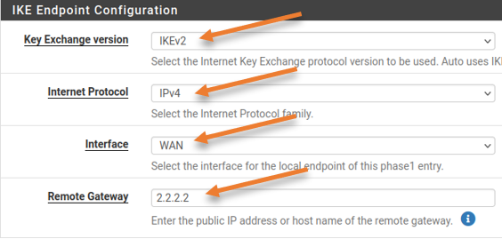
IKE Endpoint configuration:
IKE Exchange version: IKEv2.
internet protocol: IPv4.
Interface: WAN.
Remote Gateway: 2.2.2.2 ASA IP address

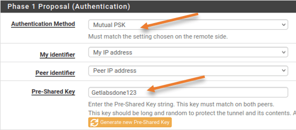
Phase1 proposal (Authentication)
Authentication method: Mutual PSK.
Pre-Shared Key: You can either enter your pre-shared key, or click on Generate new pre-shared key to create a new one. Since this is going to be a lab, I am adding Getlabsdone123 as the pre-shared key.

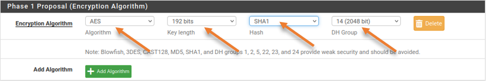
Phase 1 Proposal (Encryption Algorithm)
Both sides must match for the IPsec tunnel to come up. Enter the details as follows.
Encryption Algorithm;
Algorithm: AES
Key Length: 192bits.
Hash: Sha1
DH Group: 14.

Leave everything else default, including the Lifetime, and click on Save.
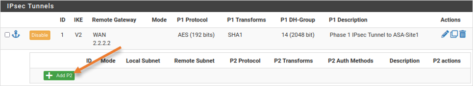
Pfsense Phase2 configuration.
The IPsec phase 2 configuration is underneath the phase 1 configuration, in the same configuration window, click on Show phase2 entries.
Click on Add P2 to add phase 2 configuration.

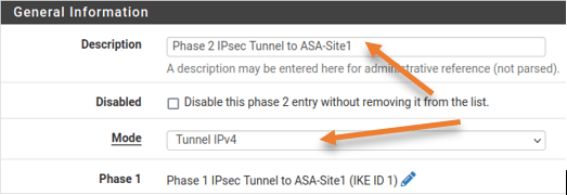
General Information;
Description: Phase 2 IPsec Tunnel to ASA-Site1
Mode: Tunnel IPv4

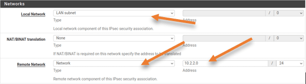
Networks
Local network: LAN Subnet.
Remote Network: 10.2.2.0/24 – This is the ASA site LAN IP address.

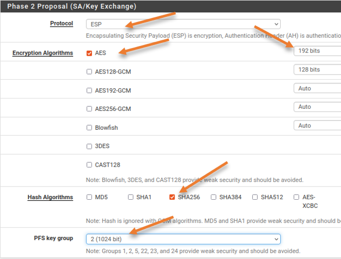
Phase2 Proposal (SA/Key Exchange)
Protocol: ESP
Encryption Algorithm: AES128
Hash Algorithm: SHA256
PFS Key Group: 2 (1024bit)
Keep the Lifetime as 3600. Leave everything else to default and click on Save -> Apply changes.

Both phase1 and phase2 are now added in the pfsense IPsec tunnel configuration.
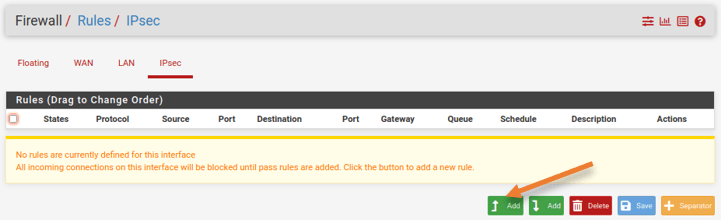
Configure security policy on pfsense.
We have set up the IPsec site-to-site tunnel in pfsense; however, to allow the communication between sites, you will have to allow the traffic coming from the IPsec to the internal LAN network.
Goto Firewall-> Rules-> IPsec
Click on the Up-Add button to add the new rule.

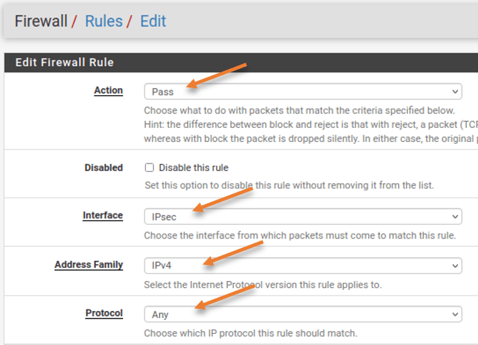
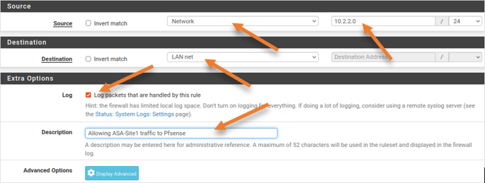
Edit firewall Rule
This rule says, Allow any IPv4 traffic coming from the IPsec interface with the source and the destination IP address.
Action: Pass.
Interface: IPsec
Address Family: IPv4.
Protocol: Any

Source: Network – 10.2.2.0/24
Destination: LAN Net
You may log the packet to see the traffic logs.
Note: By enabling logs for this traffic, it will log each session going through the firewall, which will take up some storage, so either use Syslog or add storage based on your requirement.
Description: Provide a meaningful description and click on Save.

Configure IPsec Site to Site tunnel on ASA side.
We configured ASA with the inside and outside IP addresses, and the clients on the LAN side can talk to the internet.
Let’s proceed with the IPsec configuration.
Enable IKEv2 on ASA outside interface.
The first step is to enable the IKEv2 service on the outside interface. If you don’t enable this step, the IPsec VPN will never come up.
crypto ikev2 enable outsideASA IPsec Phase1 configuration.
crypto ikev2 policy 10
 encryption aes-192
 integrity sha
 group 2
 lifetime seconds 28800
 exit
!
Phase 2 configuration.
tunnel-group 1.1.1.1 type ipsec-l2l
crypto ipsec ikev2 ipsec-proposal Sit1prp1
 protocol esp encryption aes-192
 protocol esp integrity sha-256
 exit
!
tunnel-group 1.1.1.1 ipsec-attributes
 ikev2 remote-authentication pre-shared-key Getlabsdone123
 ikev2 local-authentication pre-shared-key Getlabsdone123
 exit
!
ACL for Interesting traffic.
The IPsec tunnel we are creating is policy-based, and you are required to define the interesting traffic that needs to be allowed on the IPsec tunnel.
Define the ACL that allows traffic from the ASA LAN side (10.2.2.0/24) as the source and the destination as Pfsense LAN (10.1.1.0/24)
access-list 101 extended permit ip 10.2.2.0 255.255.255.0 10.1.1.0 255.255.255.0Configure the Cryptop map.
We will now define a crypto map calling the above parameters we defined.
crypto map mymap 10 set peer 1.1.1.1
crypto map mymap 10 set ikev2 ipsec-proposal S1pro
crypto map mymap 10 match address 101
crypto map mymap interface outside
exit
Test the VPN connectivity.
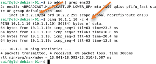
Initiate some traffic from the ASA site to the pfsense site.
As you can see, we can ping the LAN side (10.1.1.0/24) of the pfsense from the ASA LAN (10.2.2.0/24).

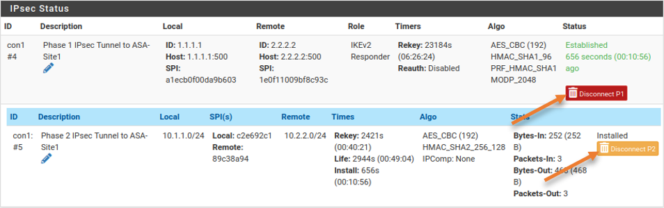
Check the IPsec Status.
We validate the connectivity by ping from one side to another, let’s check the IPsec VPN status from both the devices.
On the Pfsense side.
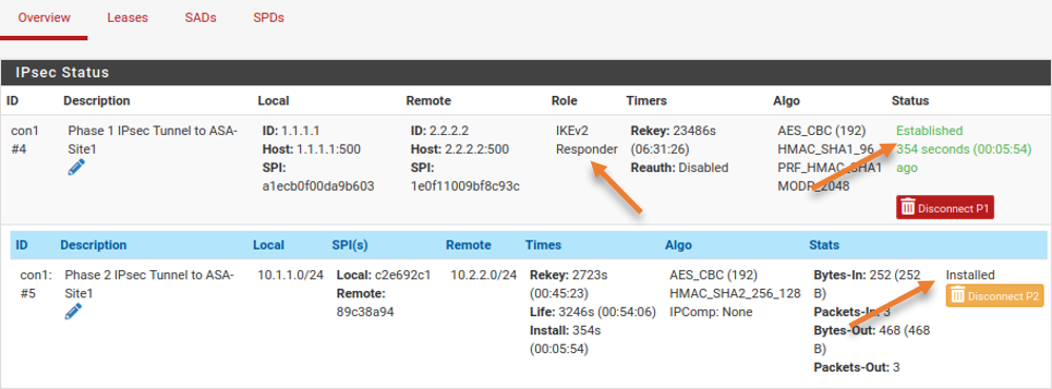
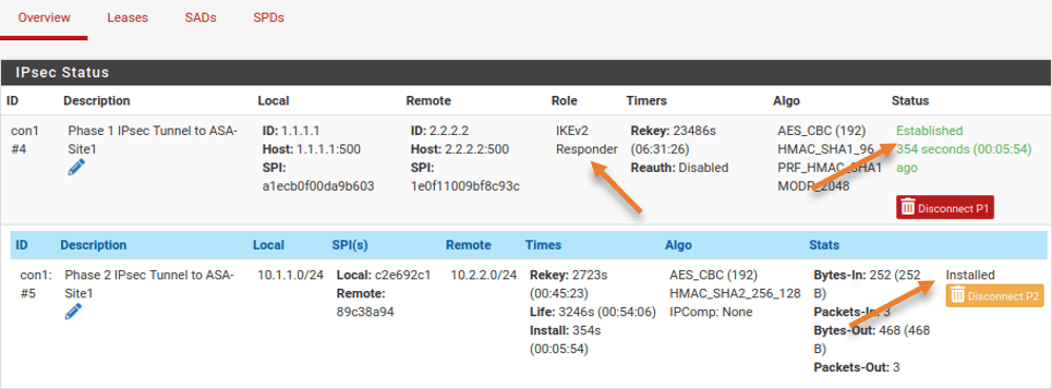
You can check the IPsec Status in pfsense by going to Status-> IPsec
You will see the tunnel is in the established state in phase1. As we have initiated the traffic from the ASA side, the pfSense phase1 is the Responder.
To see phase 2, expand the show child SA entries.
You can see, that both Phase 1 and 2 are now up.
On Cisco Side.
You can check the IPsec phase 1 status on the Cisco ASA by entering the command show crypto isakmp sa
In the role, you can see that it is the initiator because we initiated the traffic from the ASA side.
ciscoasa# show crypto isakmp sa

There are no IKEv1 SAs

IKEv2 SAs:

Session-id:24, Status:UP-ACTIVE, IKE count:1, CHILD count:1

Tunnel-id Local               Remote          Status         Role
299751203 2.2.2.2/500         1.1.1.1/500      READY        INITIATOR
      Encr: AES-CBC, keysize: 192, Hash: SHA96, DH Grp:14, Auth sign: PSK, Auth verify: PSK
      Life/Active Time: 28800/306 sec
Child sa: local selector  10.2.2.0/0 - 10.2.2.255/65535
          remote selector 10.1.1.0/0 - 10.1.1.255/65535
          ESP spi in/out: 0x89c38a94/0xc2e692c1
ciscoasa#
To see the phase 2 information, enter the command show crypto ipsec sa
ciscoasa# show crypto ipsec sa
interface: outside
    Crypto map tag: mymap, seq num: 10, local addr: 2.2.2.2

      access-list 101 extended permit ip 10.2.2.0 255.255.255.0 10.1.1.0 255.255.255.0
      local ident (addr/mask/prot/port): (10.2.2.0/255.255.255.0/0/0)
      remote ident (addr/mask/prot/port): (10.1.1.0/255.255.255.0/0/0)
      current_peer: 1.1.1.1
.
.
.
Test the network from the pfsense Side.
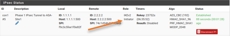
We have tested the network by initiating traffic from the ASA LAN. Let’s see what it looks like from the pfsense side.
You may go ahead and disconnect the VPN, by going into Status->IPsec
Click on Disconnect P2 and P1.

Initiate some traffic from the pfsense LAN side.
As you can see, we can now talk to the ASA LAN side from the pfsense.
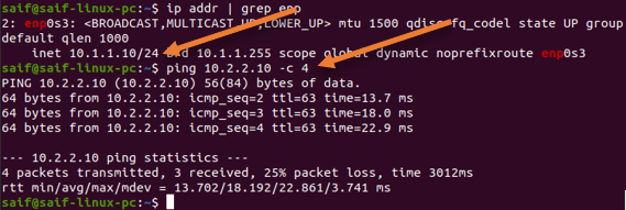
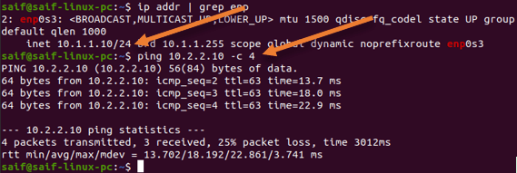
In the Pfsense side, it has become initiator, while the cisco side has become the Responder.

ciscoasa# show crypto isakmp sa

There are no IKEv1 SAs

IKEv2 SAs:

Session-id:25, Status:UP-ACTIVE, IKE count:1, CHILD count:1

Tunnel-id Local               Remote          Status         Role
301167649 2.2.2.2/500         1.1.1.1/500       READY     RESPONDER
      Encr: AES-CBC, keysize: 192, Hash: SHA96, DH Grp:14, Auth sign: PSK, Auth verify: PSK
      Life/Active Time: 28800/106 sec
Child sa: local selector  10.2.2.0/0 - 10.2.2.255/65535
          remote selector 10.1.1.0/0 - 10.1.1.255/65535
          ESP spi in/out: 0x30470e08/0xcd2835ba
ciscoasa#