The Paloalto firewall is one of the popular next-generation firewalls in the market. I like Palolalto because it is very easy to use, especially for those who come from the Cisco world.
The firewall offering from Cisco is the ASA – Adaptive security appliance. Though it provides security in your infrastructure, it lacks the features available in the next-gen firewall, such as Paloalto and fortigate etc.
You may have either of these network devices in your infrastructure, maybe you have a Paloalto firewall, and you have a request to connect another 3rd party network to your environment. And the thirty-party vendor turns out to become an ASA firewall. So how do you go about joining these two networks together?
We can use IPsec site-to-site VPN to interconnect these two networks. As you may know, IPsec is the cheap and best way to connect two different branch offices.
Keep in mind that you should not have overlapping IP addresses while connecting these networks. Let’s say you are using 10.1.1.0/24 in your Paloalto LAN network. The ASA LAN side also uses the same network, so connecting these two networks will result in overlapping IP, so you cannot really initiate a tunnel. You can either change the subnet in any of the sites or workaround that by using NAT, making it more complex.
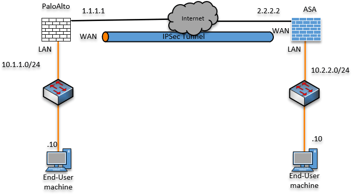
Below is the topology that we are going to work on. We have the Paloalto firewall on the left connected to the internet with the LAN subnet 10.1.1.0/24. And on the right, we have an ASA connected to the internet with the LAN subnet of 10.2.2.0/24.
At this point, both the LAN users can talk to the internet, and they cannot talk to each other.
After building the IPsec tunnel, we will verify the connectivity between these two sites.
Read also,
How to Configure IPsec Site to Site VPN Between Cisco ASA?
How to Set Up IPsec Site-to-Site VPN between FortiGate and ASA?
How to Configure IPsec Site to Site VPN Between PfSense and ASA?
How to Deploy Cisco ASAv in AWS? | Step by Step Guide.
Configure the ASA IPsec tunnel.
We will configure the IPsec site to site tunnel on the ASA side, and then we will go back to the Paloalto firewall. Whatever the changes that you make should match on both sides.
Enable IKEV2 on the outside interface.
You must enable the IKEv2 on the outside interface for the IPsec tunnel to work on the ASA. That way, the service is enabled on the external interface, and all the IPsec IKE traffic will be accepted on the firewall outside the interface.
Enter the command below to enable the IKEv2 service on the outside interface.
Configure terminal
crypto ikev2 enable outside
Configure the Phase 1 tunnel.
We will use the below parameters for the phase1.
!
crypto ikev2 policy 10
 encryption aes-192
 integrity sha
 group 14
 lifetime seconds 28800
 exit
!
Configure the phase2 tunnel.
In phase2, we will use the pre-shared key for authentication, and the pre-shared key that I use is Getlabsdone123, so based on your setup, you may define the pre-shared key.
tunnel-group 1.1.1.1 type ipsec-l2l
crypto ipsec ikev2 ipsec-proposal Sit1prp1
 protocol esp encryption aes-192
 protocol esp integrity sha-256
 exit
!
tunnel-group 1.1.1.1 ipsec-attributes
 ikev2 remote-authentication pre-shared-key Getlabsdone123
 ikev2 local-authentication pre-shared-key Getlabsdone123
 exit
!
Choose the interesting traffic with an ACL.
We need to define the interesting traffic that needs to go across the tunnel. We can define the interesting traffic with the help of an ACL. Create an ACL that permits traffic sourcing from the ASA LAN subnet to the Paloalto LAN subnet.
access-list 101 extended permit ip 10.2.2.0 255.255.255.0 10.1.1.0 255.255.255.0Configure the crypto map.
After the configuration is complete, you need to call all the parameters we defined above, create the crypto map, and assign it to the outside interface.
!
crypto map mymap 10 set peer 1.1.1.1
crypto map mymap 10 set ikev2 ipsec-proposal Sit1prp1
crypto map mymap 10 match address 101
crypto map mymap interface outside
exit
We have now completed the IPsec side configuration on the ASA. Let’s move on to the Paloalto firewall side configuration.
Set up an IPsec site to site VPN tunnel on Paloalto.
Let’s start with the phase 1 configuration of the IPsec tunnel and then phase2 on the Paloalto as well.
Paloalto Phase1 IPSec configuration – IKE Crypto.
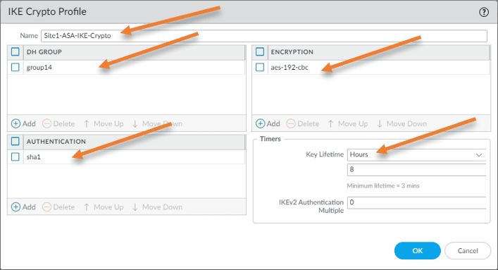
Goto Network-> Network Profiles-> IKE Crypto.
Click on Add to add a new IKE crypto profile.
Name: Site1-ASA-IKE-Crpto
DH Group: group14
Encryption: aes-192-cbc
Authentication: SHA1.
Key Lifetime: 8 Hours
Click on Ok.
Paloalto Phase 2 configuration – IPsec crypto.
Name: Site1-ASA-IPsec-Crypto
IPsec Protocol: ESP
Encryption: aes-192-cbc.
Authentication: sha256
IKE Gateways.
This is where you define the Public IP/Peer IP for the IPsec tunnel to connect.
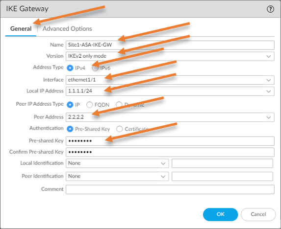
General
Name: Site1-ASA-IKE-GW
version: IKEv2 only mode
Address type: IPv4.
Interface: ethernet 1/1 – The outside interface of the firewall.
Local IP address: 1.1.1.1 Outside IP address of the local firewall.
peer IP: 2.2.2.2 – Remote ASA public IP address.
Authentication: Pre-shared key.
Pre-shared key : getlabsdone123 – enter the same preshared key that you defined on the ASA side.
Confirm Pre-shared key: getlabsdone123
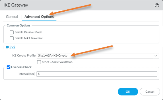
Click on Advanced Options.
IKEv2
IKE Crypto profile: Site1-ASA-IKE-Crypto
If your firewall is behind a nat device and doesn’t have a public IP address directly configured, you may choose the Enable NAT traversal.
Since I have public IP directly configured on the firewall outside interface and I am not behind the NAT, I don’t have to choose the Enable NAT Traversal option.
Click on OK.
Tunnel interface.
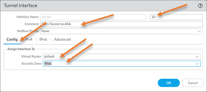
We have to configure the virtual tunnel interface in Paloalto.
Click on Interfaces-> Tunnel-> Add.
Interface name: Tunnel.10
Comment: Enter the comment to identify the tunnel interface
Config;
Virtual Router: Default – Chose your virtual router here.
Security Zone: IPsec – If you don’t have an IPsec security zone, you may click to create a new zone to add a new zone.
Click on Ok.
IPsec tunnels.
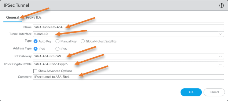
Like we created the crypto map in ASA, we need to call the phase1 and 2 configurations, IKE gateway, and tunnel interface to the IPsec tunnel that we will create.
Ipsec tunnels-> Add.
Name: Site1-Tunnel-to-ASA.
Tunnel interface: Tunnel.10
Type: Auto Key.
Address Type: IPv4.
IKE Gateway: Choose the gateway we created earlier.
IPsec Crypto Profile: Choose the crypto profile we added earlier to the palalto firewall.
Comment: Add some meaningful comment to identify the ipsec tunnel.
Add proxy IDs
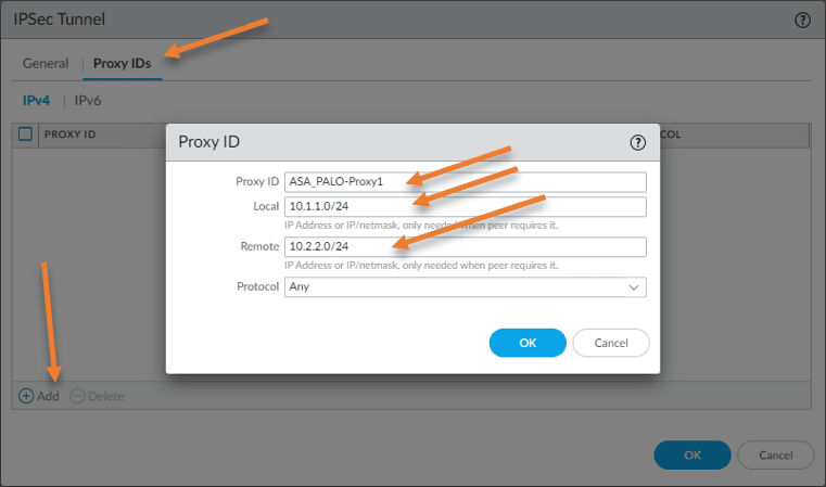
Remember in ASA. We created an ACL to filter the interesting traffic that needs to go via tunnel. Since this tunnel is based on policy based, we need to define the interesting traffic in Paloalto.
The way you would do that is by adding the proxy ID’s.
In the same IPsec window, click on Proxy ID’s -> Add.
Proxy ID: ASA_PALO-Proxy1
Local : 10.1.1.0/24
Remote: 10.2.2.0/24
Protocol: Any
click on Ok.
Static route.
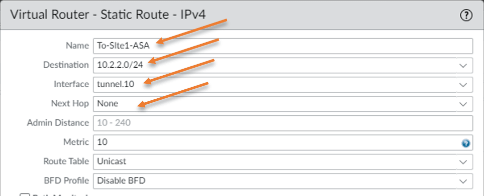
For communication between two sites, we will have to add a static route on the Paloalto to send the traffic to the ASA firewall IPsec tunnel.
Virtual Router-> Default-> Static routes.
IPv4, click on Add to add the routes.
Name: To-Site1-ASA
Destination: 10.2.2.0/24
Interface: Tunnel.10
Next hop: None – it is not required to add next hop on the tunnel interface.
Add a security policy to allow the traffic from IPsec.
We have added the static route on the Paloalto, however the communication will not be permitted, until you add the security policy.
Policies-> Security -> Add.
- General.
Name: Allow IPsec traffic. - Source zone:
Inside
IPsec.
Source Address: Any.
- Destination zone:
Inside
IPsec.
Destination Address: Any.
- Application: Any.
- Service/URL Category: Application-default.
- Actions: Allow
Click on Ok.
Test the network.
You can initiate the traffic on either side, and it should bring up the tunnel and traffic will go across the tunnel.
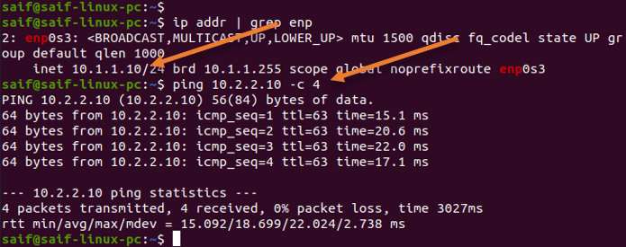
As you can see, I have logged into Palolato LAN end-user machine, and I can ping the ASA Lan side end-user machine successfully.
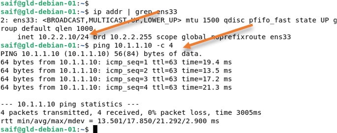
The same is true for the ASA side as well. From the ASA LAN side, I can ping the Palolato LAN side. That’s good.
Validate the IPsec tunnel.
The easiest way to check the tunnel status is from the Paloalto firewall GUE.
Goto Network-> IPsec Tunnels Here, you can see the phase1 and 2 of the tunnel status in green.
If it is red, which means the tunnel is down.

We can verify the phase1 and phase2 status on both the firewalls from the CLI.
Check the phase1 status.
In ASA, you can type show isakmp sa, it will show you the phase1 of the tunnel status. As you can see, the role is responder because we initiated the traffic from the Paloalto side. Hence Palolato will be the initiator.
gld-asa-fw-01# show isakmp sa

There are no IKEv1 SAs

IKEv2 SAs:

Session-id:5, Status:UP-ACTIVE, IKE count:1, CHILD count:1

Tunnel-id Local                 Remote                                                  Status         Role
 10779631 2.2.2.2/500           1.1.1.1/500                                              READY    RESPONDER
      Encr: AES-CBC, keysize: 192, Hash: SHA96, DH Grp:14, Auth sign: PSK, Auth verify: PSK
      Life/Active Time: 28800/4 sec
Child sa: local selector  10.2.2.0/0 - 10.2.2.255/65535
          remote selector 10.1.1.0/0 - 10.1.1.255/65535
          ESP spi in/out: 0xafe379aa/0xae5d615a
gld-asa-fw-01#
Check the Phase1 on Paloalto.
You can type show vpn ike-sa gateway <gateway name> to see the status of IPsec phase1 on Paloalto firewall. In the role you can see init, which means initiater.
admin@PA-VM> show vpn ike-sa gateway Site1-ASA-IKE-GW

There is no IKEv1 phase-1 SA found.

There is no IKEv1 phase-2 SA found.


IKEv2 SAs
Gateway ID  Peer-Address Gateway Name     Role SN  Algorithm          Established     Expiration      Xt Child  ST
----------  ------------ ------------     ---- --  ---------          -----------     ----------      -- -----  --
1            2.2.2.2     Site1-ASA-IKE-GW Init 1   PSK/DH14/A192/SHA1 Apr.07 23:57:00 Apr.08 07:57:00 0  1      Established

IKEv2 IPSec Child SAs
Gateway Name             TnID  Tunnel                               ID  Parent Role SPI(in)  SPI(out) MsgID    ST
-------  -------- -----
Site1-ASA-IKE-GW         1     Site1-Tunnel-to-ASA:ASA_PALO-Proxy1  1   1      Init A1DDD47B 67AB519E 00000001 Mature

Show IKEv2 SA: Total 1 gateways found. 1 ike sa found.


admin@PA-VM>
Check the Phase2 tunnel status.
On Cisco ASA.
To see the phase2 status of Cisco ASA, you may enter the below command.
gld-asa-fw-01# show ipsec sa
interface: outside
    Crypto map tag: mymap, seq num: 10, local addr: 2.2.2.2

      access-list 101 extended permit ip 10.2.2.0 255.255.255.0 10.1.1.0 255.255.255.0
      local ident (addr/mask/prot/port): (10.2.2.0/255.255.255.0/0/0)
      remote ident (addr/mask/prot/port): (10.1.1.0/255.255.255.0/0/0)
      current_peer: 1.1.1.1


      #pkts encaps: 7, #pkts encrypt: 7, #pkts digest: 7
      #pkts decaps: 7, #pkts decrypt: 7, #pkts verify: 7
      #pkts compressed: 0, #pkts decompressed: 0
      #pkts not compressed: 7, #pkts comp failed: 0, #pkts decomp failed: 0
      #pre-frag successes: 0, #pre-frag failures: 0, #fragments created: 0
      #PMTUs sent: 0, #PMTUs rcvd: 0, #decapsulated frgs needing reassembly: 0
      #TFC rcvd: 0, #TFC sent: 0
      #Valid ICMP Errors rcvd: 0, #Invalid ICMP Errors rcvd: 0
      #send errors: 0, #recv errors: 0
On Paloalto.
admin@PA-VM> show vpn ipsec-sa tunnel Site1-Tunnel-to-ASA:ASA_PALO-Proxy1

GwID/client IP  TnID   Peer-Address           Tunnel(Gateway)                                                                                                                Algorithm          SPI(in)  SPI(out) life(Sec/KB)             remain-time(Sec)
--------------  ----   ------------           ---------------                                                                                                                ---------          -------  -------- ------------             ----------------
1               1      2.2.2.2                Site1-Tunnel-to-ASA:ASA_PALO-Proxy1(Site1-ASA-IKE-GW)                                                                          ESP/A192/SHA256    AE5D615A AFE379AA 3600/Unlimited           3099

Show IPSec SA: Total 1 tunnels found. 1 ipsec sa found.


admin@PA-VM>