


We have covered plenty of labs related to how you can set up IPsec on Paloalto firewall to other vendors. And in this one, we will set up AWS site to site VPN tunnels towards the Paloalto firewall.
Below is the topology that we are going to configure.


By default, creating a site-to-site VPN on AWS will create two tunnels from the cloud, the first one being the primary and the second being the backup.
We already covered the AWS side of the configuration in my previous blog, and we are going to start from where we left off from my last blog. And I also explained the AWS side connectivity as well.
Let’s look at the corporate DC here. We call it Onprem DC.
- It has a subnet of 10.1.1.0/24 same subnet we configured as remote in the AWS side in the last configuration.
- Paloalto act as a customer gateway.
- Paloalto firewall is behind the NAT, so I will have to forward the IPsec port on my edge firewall.
Note: In most production deployments, the Paloalto will be located at the edge of the network, connected directly to the Internet, and have a public IP address. Paloalto is behind another router that acts as a NAT device in our setup.
Steps to configure AWS site to site VPN with Paloalto at the onprem.
1. Configure the AWS side.
We have already made the configuration on the AWS side. You may go back here and complete the AWS side of the configuration and proceed with the lab.
2. Download the AWS Paloalto VPN configuration.
I like the AWS site-to-site VPN because, when you download the VPN configuration, it will have step-by-step instructions on how you can configure the VPN on your Paloalto firewall. Those step-by-step instructions are available for most of the vendors. All you have to do is just send the configuration to the network admin in the corporate office, and they should be able to bring up the Tunnel. However, you should not blindly follow the instructions. Instead, you should tweak it based on your setup. We will look into that as well in this blog.
Let’s go ahead and download the VPN configuration then.
Goto -> Virtual Private Cloud-> Site to Site VPN connections->Download configuration.
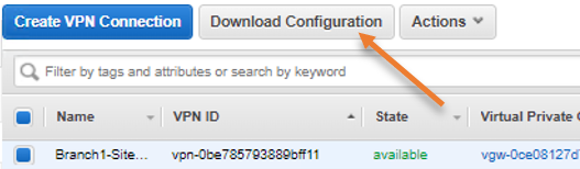
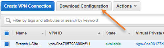
In the pop-up,
- choose the vendor as Paloalto networks.
- Platform as PA Series
- Software PANOS 7.0+
- Ike Version: ikev2
- Click on Download.
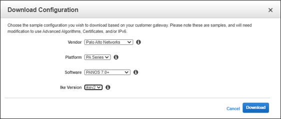

- Save the file in a safe location.
3. Proceed with the AWS Site to site VPN configuration on Paloalto.
We have downloaded the VPN configuration file to our computer.
- Open the file in notepad++ (You can open it in Notepad or your favorite text editor of your choice).
- You will see step-by-step instructions on setting up an IPsec site-to-site VPN from AWS to Paloalto.
I would recommend you go through the file and understand each item, and then go ahead and follow this guide to make sense of everything.
We will create the primary Tunnel using GUI and the Secondary Tunnel using CLI, that way, you will understand what’s happening when you type something on the CLI.
4. IPsec Tunnel 1 Phase 1 configuration on GUI.
The first step on the IPsec tunnel creation is to configure the Phase 1 parameters. Which include IKE crypto profiles and IKE gateway.
1. Configure IKE Crypto.
Login to the Paloalto firewall->Network->Network Profile->IKE Crypto.
Click on Add. A new window will pop up.
You can configure Value from your AWS VPN configuration files to the GUI.
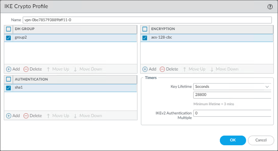
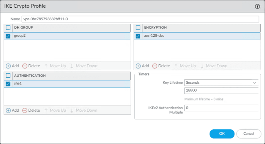
Below is my Paloalto CLI configuration of IKE Crypto from AWS.
edit network ike crypto-profiles ike-crypto-profiles vpn-0be785793889bff11-0
set dh-group group2
set hash sha1
set lifetime seconds  28800
set encryption aes-128-cbc
Which translates to,
- Add the name as vpn-0be785793889bff11-0
- Choose the DH Group as group2.
- Set the Authentication as SHA1.
- Choose the lifetime as 28800 seconds.
- Set the Encryption as AES-128-CBC.
2. Configure the IKE Gateway.
We can configure the IKE gateway in IKEv1 and IKEv2. In IKEv2, we can configure it as IKEv2 preferred mode and IKEv2 only mode.
On the AWS side, we had configured the IKE as IKEV2, and we will choose IKEv2 only mode, hence following the configuration for the IKEv2 only mode.
In Paloalto -> Network->IKE Gateways-> Add.
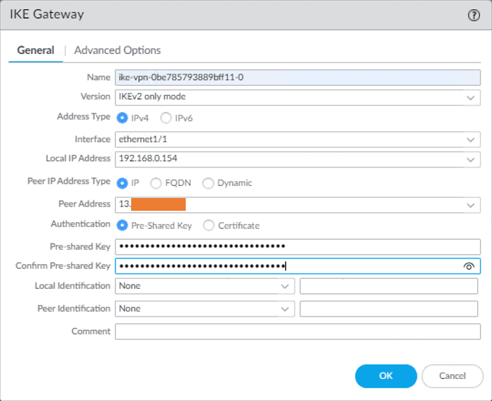
1. IKE Gateway General configuration.
In the IKE Gateway window, configure the IKE Gateway configuration in the General tab by looking at the downloaded configuration.
- Name the IKE gateway : ike-vpn-0be785793889bff11-0.
- Version : IKEv2.
- Interface: Ethernet1/1 (Outside interface that connected to the Internet).
- Local IP address: Choose the Outside local IP.
- Authentication: Choose Pre-shared Key.
- Preshared Key: Enter the pre-shared key we got from the AWS.
- Confirm pre-shared key : Confirm the same preshared key.

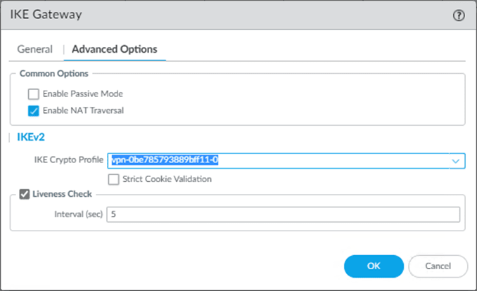
2. IKE Gateway Advanced Options.
Once the IKE Gateway General configuration is completed, you can click on the Advanced options.
- If your firewall is connected directly to the Internet and has a public IP address on your firewall outside interface, leave the Enable NAT traversal option Unchecked.
In my case, the firewall is located behind a NAT device, and it has a private IP address on the edge of the firewall, so I have to choose Enable NAT Traversal.
Note: You also need to enable Port forwarding and forward port 4500 towards the Paloalto outside interface if the AWS side is initiating the connection.
If only the on-prem side is initiating the traffic, you don’t have to make any changes on the port forwarding.
Follow the article below to learn more about how you can configure port forwarding on Pfsense firewall and a router.
Port Forwarding in Router – How to Configure?
How to Configure PfSense Port Forwarding?
How To Configure OPNsense Port Forwarding?
- Under the IKE crypto profile, choose the profile that we created earlier.
- Liveness Check interval to 10.
Below is what my advanced configuration look like, click on OK here.

5. IPsec Tunnel 1 Phase 2 configuration on GUI.
We now have to configure Phase 2 of the Site to Site VPN towards the AWS.
1. Configure the IPsec crypto.
In paloalto firewall Under Network-> Network Profiles-> IPsec Crypto->Add.
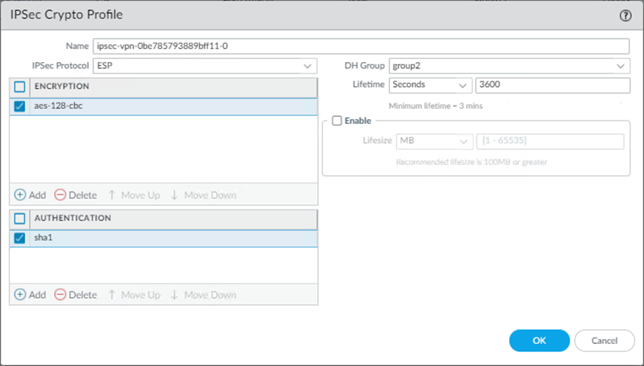
Configure the IPsec crypto as per the configuration file.
- Name the IPsec Crypto as ipsec-vpn-0be785793889bff11-0.
- Choose the Encryption as aes-128-cbc.
- Authentication as sha1
- DH Group as group2.
- A lifetime as 3600 seconds.

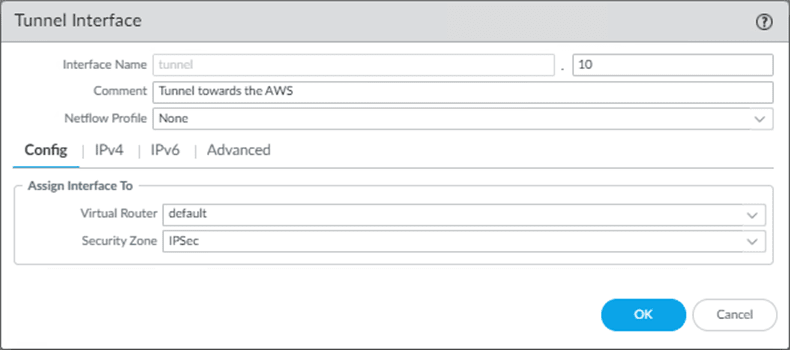
6. Configure the Tunnel interface.
In AWS tunnel configuration, it is trying to create an interface which is tunnel.1, and I am already using tunnel.1 in my firewall. So in production, you must change it according to your environment, as tunnel.1 might have already been picked up by either GPVPN or other IPsec tunnels. I am going to choose the Tunnel.10 instead.
You will mostly have a security zone dedicated to the IPsec tunnels, so you may choose that one instead of the Untrust zone in configuration. And if you don’t have a security zone, you may create one called IPsec and keep it ready.
We need to associate the tunnel interface with a router in the configuration. In production, it is most likely that you must have changed the virtual router name from default to something else, so you need to make sure you call that virtual router name instead of the default.
However, the router name is still a ‘default’ in my configuration, so I should be okay.
In Paloalto->Network->Interfaces->Tunnel->Add
Config
- Add the tunnel interface as 10.
You may add a comment if needed.
- Choose the default router. In my case, it is the default.
- Choose the security zone – Which is IPsec in my firewall.

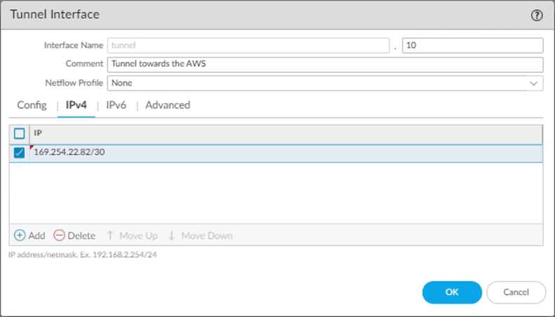
IPv4
Click on IPv4 and add the IP address from the configuration.

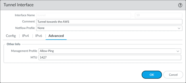
Advanced
- In the advanced tab, you may add any management profile you have created for the Tunnel. This is optional though, and click on OK.
- Change the MTU to 1427.

7.Configure the IPsec tunnel.
Finally, we will call all those phase 1 and 2 configurations and create an IPsec tunnel.
Goto Network->Ipsec tunnels-> Add.
- Name the IPsec tunnel as ipsec-tunnel-1
- Choose the tunnel interface as Tunnel.10, Remember, we changed the tunnel interface from 1 to 10 due to conflict.
- Choose Type as Auto Key
- Address type as IPv4.
- Choose the IKE gateway that we have created.
- And the IPsec Crypto profile we defined earlier and click on Ok.
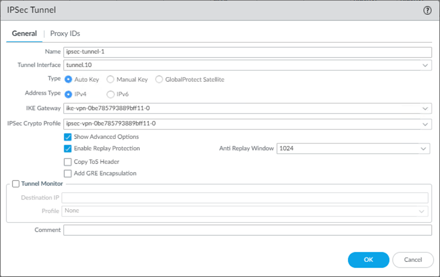
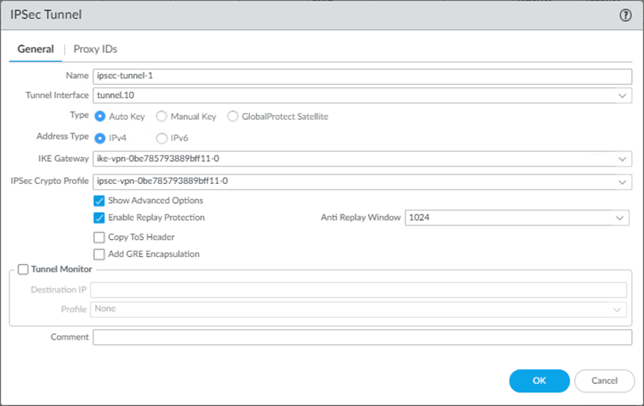
You will see the Tunnel is currently down, which is expected, nor do we commit the changes yet.


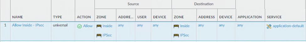
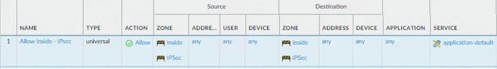
8.Configure the Policy for IPsec tunnels.
For the communication to happen from inside to IPsec and vice versa, you need to add the policy to allow IPsec traffic to pass.
The on-prem host is in the Inside zone of the firewall, and the AWS is in the IPsec zone. By default, the communication between different zones are blocked. So you need to allow them to make the communication happen.
Policies-> Security-> Add.
General,
Name the policy : Allow Inside – Ipsec
Source
Source Zone
Inside, IPsec.
Destination
Destination zone
Inside and IPsec.
Application: Any
Service/URL category : Application default.
Actions:
Action Settings:
Action: Allow.
Click on OK.
Below is the snippet of the rule.
With the above configurations, your primary Tunnel towards the AWS should come up, you may go ahead and commit the changes and you should be able to initiate the communication, we will test that after building both the tunnels.
9. Policy Based Routing with Tunnel monitor.
In the AWS site-to-site VPN, we create two tunnels, only one Tunnel will be forwarding the traffic at at a time, we are achieving that using Policy-based routing with tunnel monitoring.
The policy-based forwarding rule with tunnel monitor is created for the primary Tunnel now, tunnel.10. We will make another policy for the secondary Tunnel after the secondary Tunnel is implemented.
Why can’t I use the static route instead?
Suppose you create a static route pointing to the Tunnel, and any problem with the primary Tunnel doesn’t automatically failover to the secondary. So we will have to use Policy-based routing with a tunnel monitor, so when the traffic is destined for a specific location and if the tunnel monitor IP becomes unreachable, the policy will be disabled, and the second policy will kick in. Instead of using the routing, we control the routing using the policy. Hence, called the Policy-based forwarding rule. It works similarly to security policy from top to bottom.
Note: We can also achieve the same result using static route monitoring, but we will stick with the PBR.
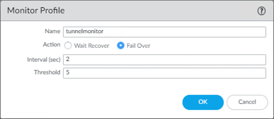
1. Create a tunnel monitor.
We have to create a tunnel monitor that we will attach to the policy later.
Goto Network-> Network profiles-> Monitor->Add.
- Choose the name for the tunnel monitor, I am choosing the default name.
- Action as Failover.
- Interval in sec as 2.
- Threshold as 5.
Add the config as below and click on OK.

2. Configure the Policy-based forwarding.
The default AWS PBR configuration for Paloalto calls the source zone inside and the address as the OnPrem-CIDR, so the routing will not work if you want your AWS private subnet host to communicate to the Internet via On-prem.
- When the Private subnet host tries to reach the Internet, the traffic will come via IPsec tunnel->One-Prem->Internet.
- The return traffic will come from the Internet (Outside zone), and the firewall will allow the traffic as it has a state entry for that traffic.
- Though return traffic is allowed through the firewall, sourcing from the outside zone with a public IP doesn’t know how to get back to IPsec. As there is no route pointing back to the AWS side via IPsec. As per the AWS PBR configuration, we only accept the traffic sourcing from Inside and the LAN private IP address. However, traffic from Internet is from outside zone with a Public source IP. And we don’t have a policy for that.
- We need to tweak the PBR policy (Source)for this to work.
Policies->Policy Based Forwarding->Add.
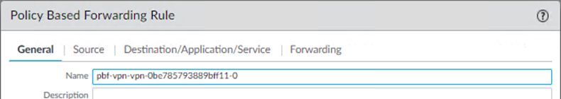
General
Enter the name for the policy.

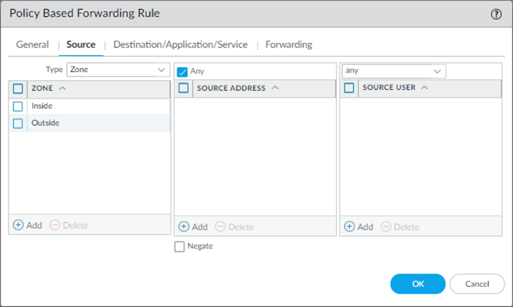
Source.
- Choose inside and Outside as the source zone.
- Leave the Source address blank.
Note : Just because we call the Oustide zone in the policy with any address doesn’t mean that all outside traffic will be allowed. Because we don’t have any policy that allows outside traffic to in, neither any NAT policy. This PBR will only accept the outside traffic only firewall allowed the traffic using it’s state entry.
Do not ever allow outside traffic to inside in the SECURITY POLICY. Unless you allow specific public IP that you trust.

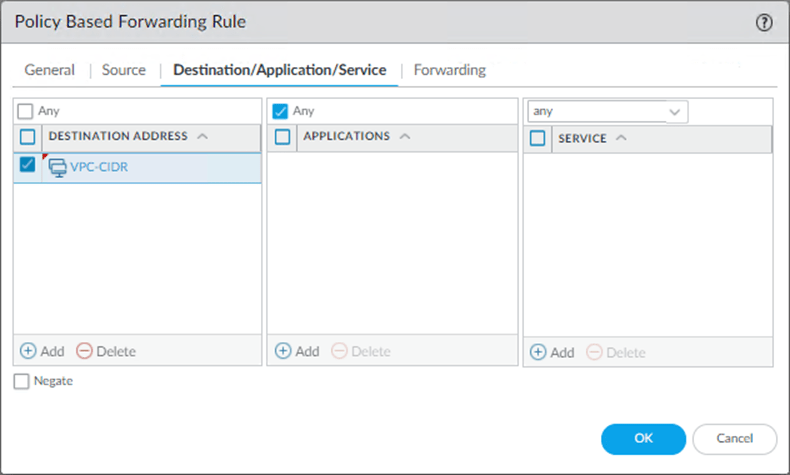
Destination/Application/Service.
- Add the Destination Address as
- VPC-CIDR
- Application and Service to – Any.

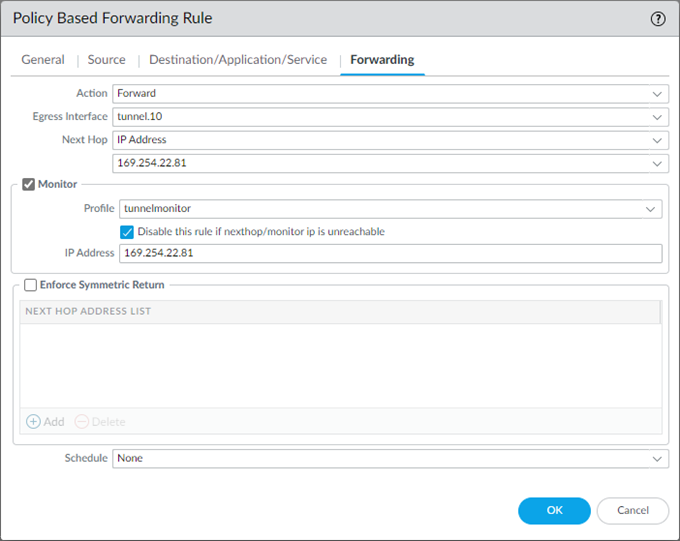
Forwarding.
- Action : Forward.
- Egress interface : Tunnel.10
- Next Hop : IP address : 169.254.22.81
- Check the monitor option.
- Profile : Call the tunnel monitor profile that we created earlier.
- Check the option to disable this rule if nexthop/monitoring ip is unreachable.
- IP Address 169.254.22.81, and click on OK.

We have now completed the Tunnel one configuration. Let’s move to the second Tunnel towards the AWS, using the CLI.
10. AWS site to site VPN to Paloalto – tunnel configuration Using CLI.
We were able to complete the first tunnel configuration through the GUI, while doing so, it made a lot of sense on the CLI configuration.
Now, let’s configure the AWS second tunnel using CLI to save some time. The CLI is the fastest and easiest way to configure the IPsec tunnels on Paloalto. Provided you should know what you are doing.
1. Phase 1 secondary Tunnel configuration to AWS.
Like we did before, lets go ahead and configure the IKE-Crypto.
IKE-CRYPTO
Below is the IKE-Crypto configuration from AWS, there is no change needed here, hence you can simple copy and paste the configuration on the Palo.
configure
edit network ike crypto-profiles ike-crypto-profiles vpn-0be785793889bff11-1
  set dh-group group2
  set hash sha1
  set lifetime seconds  28800
  set encryption aes-128-cbc
  top
IKE-GATEWAY.
We will use the IKEv2 only mode, so we are going to get the IKEv2 only mode configuration.
I have changed the configuration based on my network.
- Changed the Nat traversal to Yes.
- IKEv2 require-cookie no.
- In the local address, AWS configured my public IP, that’s not true because I am behind a NAT device, hence I need to configure my private outside IP address.
- After that just past the configuration.
edit network ike gateway ike-vpn-0be785793889bff11-1
set protocol version ikev2
set protocol ikev2 ike-crypto-profile vpn-0be785793889bff11-1
set protocol ikev2 dpd enable yes interval 10
set authentication pre-shared-key key lW.O1w3p6v58u9lODcXcOqPZp2A.pELE
set protocol-common nat-traversal enable yes
set protocol ikev2 require-cookie no
set local-address ip 192.168.0.154
 set local-address interface ethernet1/1
 set peer-address ip 52.x.x.x
 top
2. IPsec Phase 2 Configuration
Ipsec Crypto.
We are now getting into the phase2 of the ipsec configuration.
You can copy and paste the same configuration from the AWS.
edit network ike crypto-profiles ipsec-crypto-profiles ipsec-vpn-0be785793889bff11-1
  set esp authentication sha1
  set esp encryption aes-128-cbc
  set dh-group group2
  set lifetime seconds 3600
 top
Tunnel creation.
We will create a tunnel and add that tunnel interface into the IPsec zone and to my virtual router.
The default config from AWS will not work, so I will have to make some changes.
- We are not going to use tunnel.2 for the IPsec, previously we had taken tunnel.10, so I will choose Tunnel.11 here.
- Choose the zone as IPsec. That’s where I have kept all my IPsec tunnels and the tunnel interface as Tunnel.11.
Note: The zone name is case sensitive, so you need to type exactly what you have on the firewall.
- Leave the virtual router as default. However tunnel interface should be Tunnel.11
edit network interface tunnel units tunnel.11
  set ip 169.254.26.138/30
  set mtu 1427
 top
 set zone IPSec network layer3 Tunnel.11
 set network virtual-router default interface tunnel.11
3. IPsec tunnel creation.
We have to call all the parameters we defined above and create an IPsec tunnel.
Like before, I have made the changes on the configuration as per my setup.
- Change the tunnel interface on the configuration, that’s the only change this time.
edit network tunnel ipsec ipsec-tunnel-2
  set auto-key ipsec-crypto-profile ipsec-vpn-0be785793889bff11-1
  set auto-key ike-gateway ike-vpn-0be785793889bff11-1
  set tunnel-interface Tunnel.11
  set anti-replay yes
 top
You will see the Tunnel is now created.


4. Create PBR for the secondary Tunnel.
We have already created a tunnel monitor profile. With that profile, let’s go ahead and create a Policy-based forwarding.
Like we have made the changes on the PBR using GUI, calling both the Inside and outside zone as source with IP address any, we will do the same configuration on the CLI as well.
I have made the changes to the following.
- Set action forward egress-interface to Tunnel.11, which is our secondary Tunnel.
- Set source from any with zone inside and outside.
edit rulebase pbf rules pbf-vpn-vpn-0be785793889bff11-2
  set action forward nexthop ip-address 169.254.26.137
  set action forward egress-interface tunnel.11
  set action forward monitor profile tunnelmonitor disable-if-unreachable yes ip-address 169.254.26.137
  set source any source-user any destination VPC-CIDR application any service any
  set from zone Inside
  set from zone outside
  set disabled no
 top
Commit the changes by typing Commit on the CLI.
It will take some time for the Commit to finishing.
Test the connectivity from the Onprem host.
Oh! That was a long configuration, wasn’t it?
We need to ensure all the pieces we configured work together as they should.
From your corporate host, which is 10.1.1.10 IP, try to ping both the Private and public hosts.
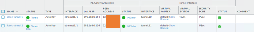
As you can see, I can ping from my local host to the remote AWS private and public host, and as soon as we initiated the traffic, the IPsec tunnels also came up now.

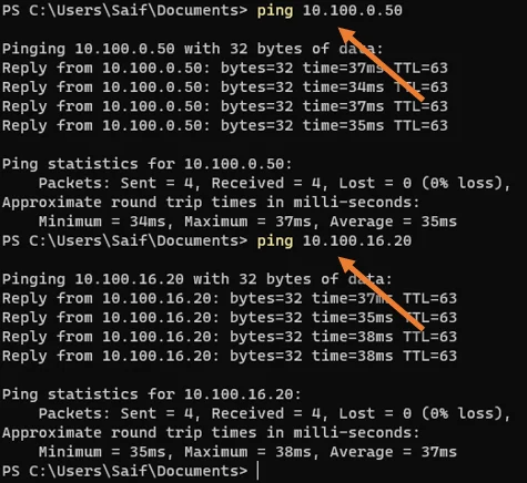
See both the Tunnel turned from RED to green.

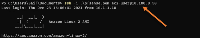
Validate the SSH access to the AWS public and Private host.
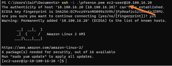
We can ssh into the private host, As the security group allows all traffic to the private host.
Note: We allowed all the traffic because there is no internet traffic allowed from the AWS side and the Internet that is permitted through IPsec already has a filter in place at the firewall.

How about a Public host?
Usually, we ssh into the public host via the Internet using public IP address, and this time let’s try to ssh using the private IP address.
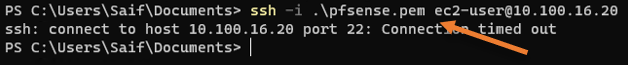
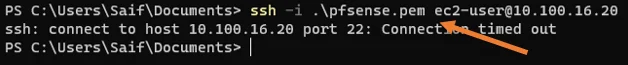
Even though I can ping the host in the public subnet, I cannot ssh into it.
This means network availability is okay. However, the aws is not allowing the traffic.
So if you followed my VPC public host creation article, you must have ssh access restricted to your public static IP.
We need to allow access from our branch1 subnet, 10.1.1.0/24, to ssh into the public host.
I added a new rule that says it is allowed if you ssh from the source IP 10.1.1.0/24 that’s our corporate subnet.


Save the rule and test again. You should be able to log in to the public host now.
As you can see, this time, I could ssh into the AWS ec2 instance in the public subnet from my branch1 subnet.

Verify the internet connectivity from Public and Private hosts.
As per our diagram, the devices in the private subnet should go via an on-prem firewall to get to the Internet; similarly, the host in the public subnet should be able to go to the Internet via AWS’s internet gateway.
1. Internet access from Privat host.
Let’s check the internet connectivity from the Private host first.
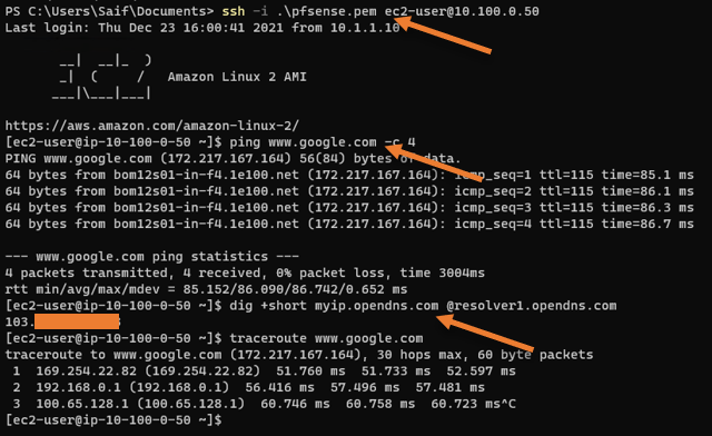
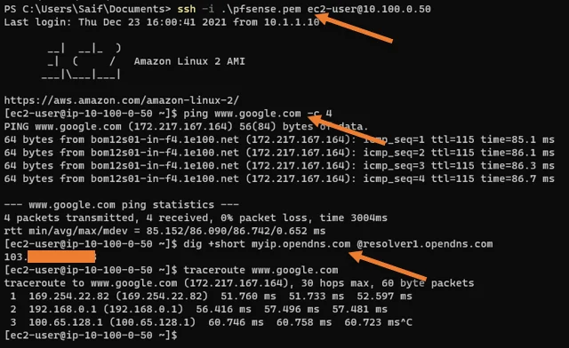
From the output above,
- I can ping the Internet.
- The private host’s public address shows Onprem static IP address.
Use the command dig +short myip.opendns.com @resolver1.opendns.com to know the public internet IP.
- Traceroute shows internet traffic is going via on-prem firewall.
2. Test the internet access from public host.
We know that the public subnet host will have internet traffic offloaded from the AWS, which we verified during the public subnet creation. All we have to check here what is the NAT’d IP.
As you can see, it is pointing to the NAT’d IP address from AWS, which proves that the public host is going to the Internet via AWS.


3. Check the traffic on Paloalto.
You can confirm the traffic going across the Tunnel in Traffic monitoring in Paloalto.
And as you can see, all the traffic is going via tunnel.10.
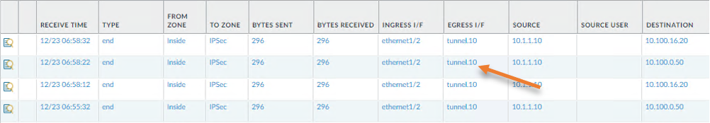
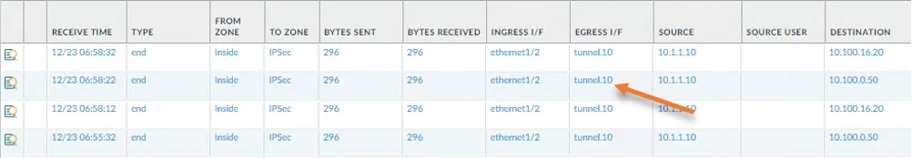
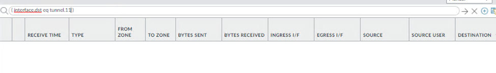
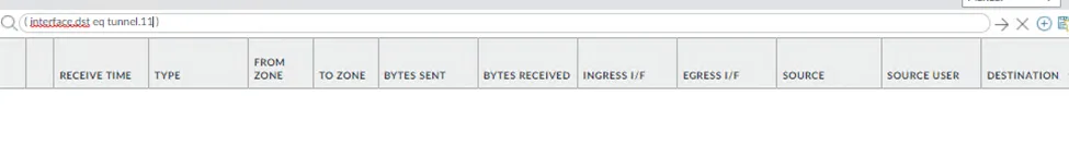
We cannot see any traffic going via tunnel.11 which says tunnel 10 is the Primary.
4. Check the failover.
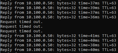
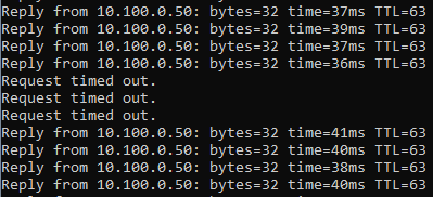
Do a continuous ping to any one of the VPC hosts, and disable the primary Tunnel (tunnel.10) and see how it behaves.
To disable the primary Tunnel.
Network -> IPsec tunnels ->Select IPsec Tunnel 1
Click on Disable, and commit the changes.
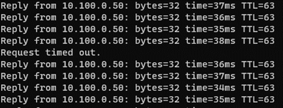
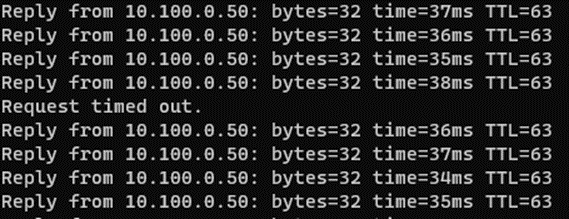
As you can see, there was a three request time out for pings since it was committed, and the traffic failed overed to tunnel.11 that is pretty good.
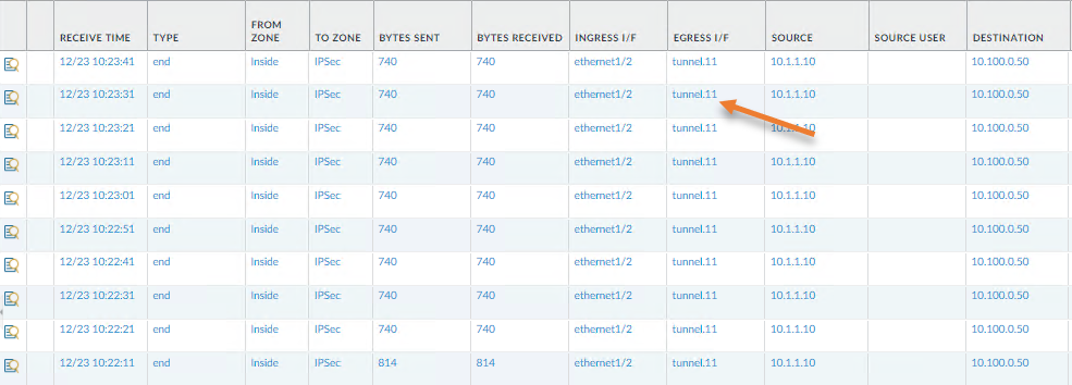
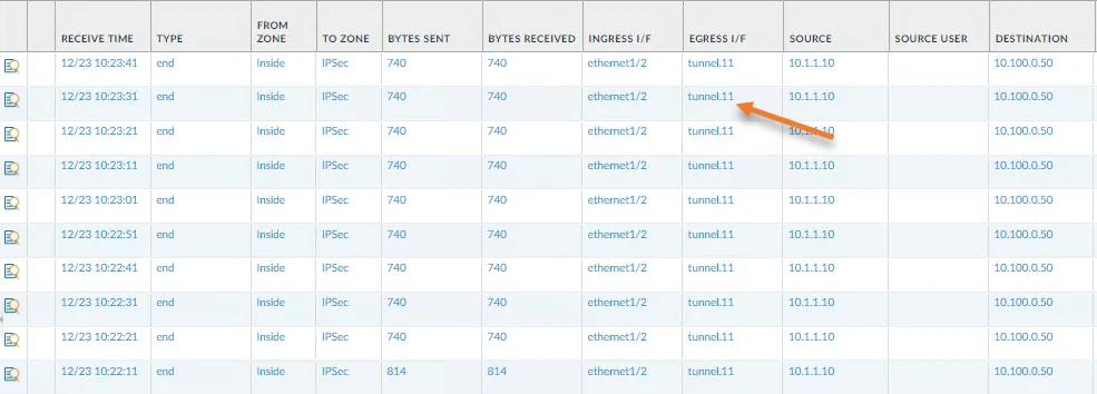
You can verify the same from the firewall monitoring as well, and this time it should show the traffic towards the Tunnel.11
And you can see the traffic destined to the VPC is now going via the Tunnel.11
Let’s bring back the primary Tunnel.
Go back to the IPsec tunnels, choose the IPsec tunnel-1, and click on enable.
And commit the changes.
As soon as the Tunnel came up, traffic switched to the primary Tunnel (tunnel.10), and it was almost instant, and we saw only a single packet loss which is excellent.
And from the monitoring, it is clear that the traffic is now going via the secondary Tunnel.
How do I make Secondary Tunnel Primary?
The way we are routing the traffic is using Policy-based forwarding, right? So to make tunnel.11 as the Primary, you move the second PBR policy that we defined for tunnel.11 to up. As soon as the firewall hit the Tunnel.11 PBR policy and if the tunnel monitor IP is reachable, it will choose that path.
Current configuration with Tunnel.10 being primary.
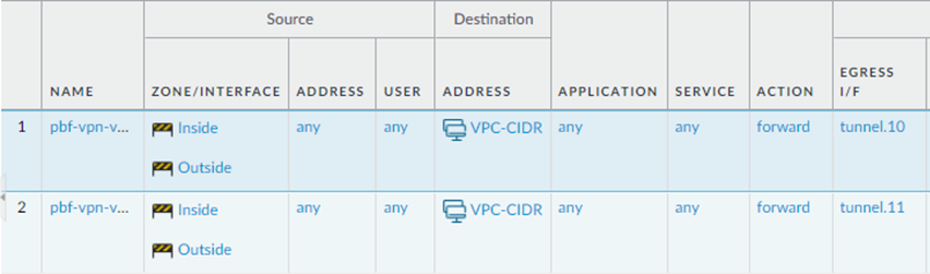
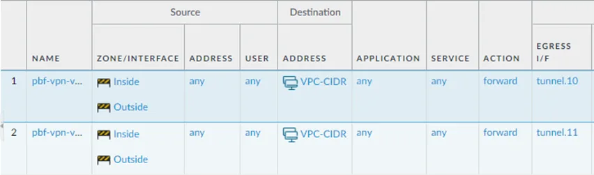
Moved the tunnel.11 policy up to make tunnel.11 as Primary.
Rolando Contreras
Sunday 25th of February 2024
At this time what I expect is to have more security for my PC and personal information. I do not have secret information but pretend to be safety of hackers and fakers.