
We have installed Proxmox in one of our servers in our last blog post, but it had only a single interface, so we configured the VLAN to send multiple traffic, which is good if you have a smaller network or a lab. However, you cannot run the server with a single interface in a production environment. As your network grows, it is crucial to have reliability and redundancy in your network. So how do you increase the network performance in the Proxmox server?
You can improve network performance on the Proxmox server by adding more network interfaces. Just adding the network interfaces will not do any good. You have to team those interfaces properly to take advantage of your network setup. The very common way to configure teaming/bonding in the network is by using the LACP protocol.
If you are from a network background, the bonding has a different name, such as Link aggregation, bridge aggregation, port-channel, ether channel. However, most server admins call it bonding, teaming, bundling the interfaces, etc. We will call bonding and port channels when configuring the server and the switch side respectively.
What is LACP bonding in Proxmox?
In Proxmox, you can achieve network performance by increasing the network interfaces, bonding them together, and creating a bridge with those multiple interfaces, thus providing aggregate bandwidth from the link. There are multiple protocols available for you to configure the bonding protocol. The typical standard protocol supported by most network equipment and the Proxmox server is LACP – Link aggregation protocol.
Many users new to Proxmox get confused and do not know what to create first when creating the bond interface, whether to create a bridge or bond or even a VLAN interface, eventually end up unable to connect the virtual machine to the network. Hopefully, at the end of this article, you will get a clear picture of how you can successfully set up bonding in Proxmox using an LACP protocol.
In Proxmox, you configure the bond interface with LACP protocol, making those physical interfaces members. After that, you create a bridge interface that you can connect to the virtual machines.
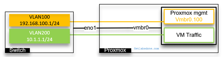
Below is our current network with a single interface that carries multiple VLAN traffic.

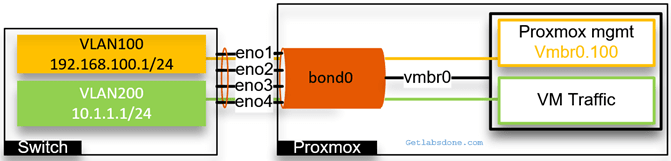
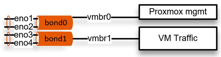
Below is what it looks like when you configure a bonding with Proxmox.
With bonding, though we have 4 physical interfaces but from the server and switch perspective it a single logical interface.

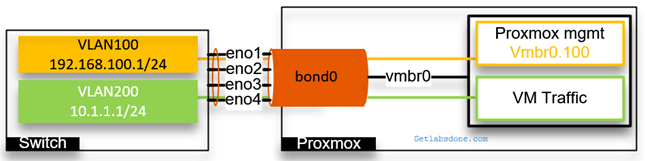
Let’s suppose one physical interface is capable of 10GBps, and The bond interface will provide the aggregate bandwidth of 40GBps. Not only that, it will also give redundancy to your server. For example, if any of the physical ports were to go down rest of the other ports would carry the traffic.
In this blog article, we will look at a single bond configuration that carries both the Proxmox management traffic and the VM traffic. Later, we will split those networks by tagging VLAN. Afterward, we will create two bond interfaces, one for management traffic and the second is for VM traffic, by using VLAN tagging.
If you use VLAN tagging, you also require a layer3 switch if you want to allow inter-VLAN communication. I am using a cisco layer 3 switch in this lab.
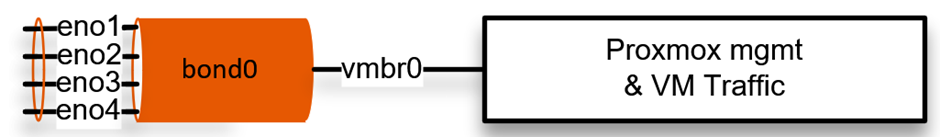
Proxmox bridge multiple ports using a single bond.
We have four physical interfaces connected to the server, and we will configure it as a single logical interface called bond0. For the VMs and Proxmox management to connect to the interface, we use bridge interface vmbr0. And configured the vmbr0 interface as an access port for VLAN 100.
Let’s configure the bond0 interface in our setup. First, we will configure the LACP configuration on the switch and then on the Proxmox server.
1. Create the port-channel and configure it as an access port.
If you have a stack switch, you should take the first two ports from the first stack member and the second pair from the second member, so when any of the stack members goes down, you always have connectivity, like I am doing below.
We will configure the VLAN as an access port as well.
enable
Configure terminal.
!
vlan 100
exit
!
interface vlan 100
ip address 192.168.100.1 255.255.255.0
exit
!
int range g1/1, g1/2, g2/1, g2/2
channel-group 1 mode active
exit
!
interface port1
switchport mode access
switchport access vlan 100
exit
!
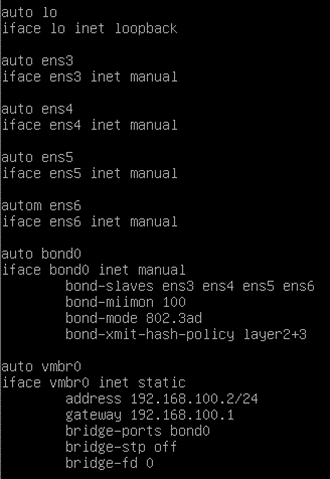
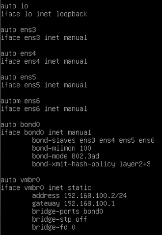
Let’s go ahead and configure the bond interface on the Proxmox server; the interface configuration is in the /etc/network/interfaces file.
Use nano or vim utility and edit the file as below.
We have CLI access to the Proxmox server.
2. Define the physical interfaces.
You must have all the interfaces added in the config.
auto ens3
iface ens3 inet manual
auto ens4
iface ens4 inet manual
auto ens5
iface ens5 inet manual
autom ens6
iface ens6 inet manual
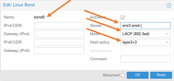
3. Configure the bond0 interface.
We don’t configure the Ip address on the bond interface either, we define the bond interfaces.
Add all those physical ports as slaves.
The next three lines are for the LACP configuration.
auto bond0
iface bond0 inet manual
	bond-slaves ens3 ens4 ens5 ens6
	bond-miimon 100
	bond-mode 802.3ad
	bond-xmit-hash-policy layer2+3
4. Create the bridge interface.
Finally, we are going to create a bridge interface that will carry both the Proxmox management traffic and the VLAN traffic.
- Since we had to configure the IP address, we added static at the end.
- Defined the IP address and gateway.
- Made the bridge port as bond0.
I am not using STP. Hence turned it off. You may turn the spanning tree on or off based on the requirement. Which is used to avoid loops.
auto vmbr0
iface vmbr0 inet static
	address 192.168.100.2/24
	gateway 192.168.100.1
	bridge-ports bond0
	bridge-stp off
	bridge-fd 0
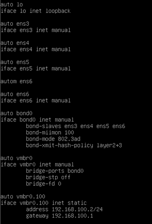
And here is the final bond configuration from the Proxmox server.
You may go ahead and restart the network service with the command, service network restart.
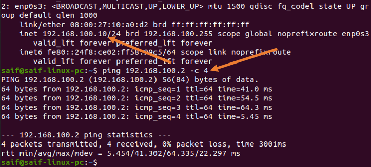
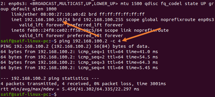
5. Verify the network.
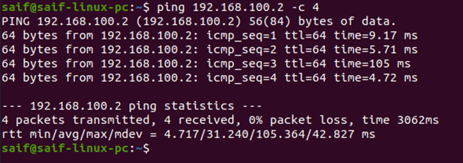
From the management PC, you may try to ping the IP address, You should get a response for the Proxmox management IP address.
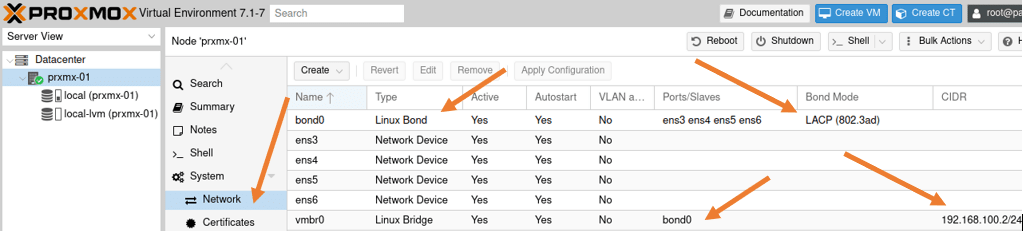
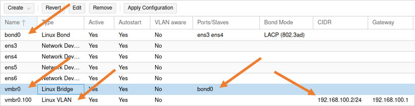
Validate the network configuration in the GUI.
Access the web GUI, and go to the host->System->Network.
You will see the bond interface configuration here. We are not using VLAN aware because we are using a VLAN access port (untagged port).
We will use VLAN aware option when we use VLAN tagging on the bond interface. Learn more about the VLAN configuration on Proxmox here.

When you create a virtual machine in this setup, all the virtual machines will be from the same subnet 192.168.100.0/24.
If you want to separate VM and the management traffic, you need to use VLAN tagging. Let’s look at the bonding interface with VLAN.
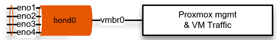
Proxmox single Bond interface with VLAN.
We have a single bond interface created. If you want to separate the different networks such as Proxmox management and the VM traffic, you can use VLAN tagging. We have covered the VLAN configuration with a single interface in more detail here. We will see the same configuration with the bond interface.
After the configuration, you will have two VLAN gateways in the switch, one for the Proxmox management and the second VLAN is for the VM traffic.
We will make the port channel tagged, and we will also tag the VLAN on the Proxmox side.

Let’s go ahead and proceed with the VLAN configuration on the Bond interface.
1. Configure the bond interface with VLAN tagged on Proxmox.
You most likely will have GUI access to the Proxmox server. Follow the steps below to configure the VLAN tagged on the bond interface. If you don’t have GUI access, scroll down to see the CLI configuration.
Login to the Proxmox, choose the host where you are making the changes.
Click on the host machine-> System-> Network
We already have a bond interface created with the LACP, if not go ahead and create the bond interface.
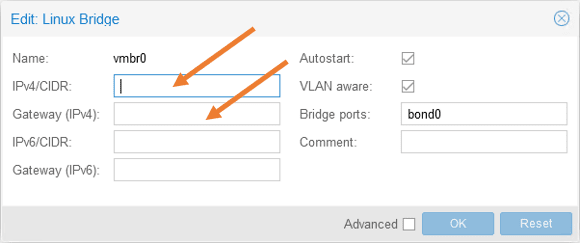
Previously, we created the bridge interface with IP address, let’s go ahead and remove the IP address from the VMbr0 interface, we will add this ip address later to the VLAN tagged interface.
- Double click on the vmbr0 bridge.
- And remove both the IP address and its gateway.

2. Configure VLAN 100, and its IP address on the bridge interface vmbr0.
We configure an IP address and the gateway because this bridge interface will act as a management interface for Proxmox.
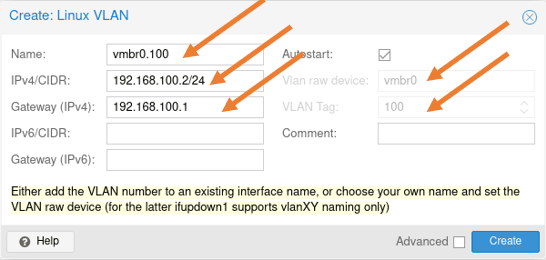
Click on Create-> Linux VLAN
In the pop-up, configure as below.
Name: Enter the name of the bridge interface. Here you can add the VLAN as sub-interface name, if you just add the vmbr0, you will have an option to add the VLAN tag separately, since the sub-interface name already has a VLAN number, Proxmox already picked up the VLAN tag.
IPv4/CIDR: Enter the Proxmox management IP.
Gateway: Enter the gateway for the IP.
And click on Create.

The CLI configuration.
Below is the configuration that we just made from the CLI.

Note: you will lose the network connectivity to the Proxmox server after performing the next step if you have logged into the Proxmox remotely.
Go ahead and restart the network service on Proxmox with the command service network restart.
3. Configure the VLAN and tag it on the port channel in the switch.
We already have VLAN 100 created previously. Let’s go ahead and create another VLAN 200 for the VM traffic.
Configure the VLAN 200 on the Switch.
Enable
configure terminal.
vlan 200
interface vlan 200
ip address 10.1.1.1 255.255.255.0
exit
Configure the port-channel as VLAN tagged.
First, I will set the port-channel 1 interface to its default configuration because it was configured as access port before; that’s the easiest way to remove the old config from the cisco switch.
gld-sw-01(config)#default interface po1
Interface Port-channel1 set to default configuration
And I will configure port-channel 1 as a trunk and allow only the VLAN 100 and 200 as tagged.
Configure terminal
interface port-channel1
switchport mode trunk
switchport trunk allowed vlan 100,200
exit
Verify the network connectivity.
You can start testing the connectivity by pinging the management host to the Proxmox server.
Note: for the management pc to talk to the tagged VLAN 100 on the Proxmox server, you first need to configure the management PC port that is connected to the switch as an access port on VLAN 100.
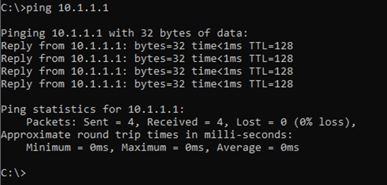
As you can see, from the management PC, I can now ping the Proxmox server.
To test the VM traffic, you can go to any VM, click on hardware, change the network to vmbr0, and in the VLAN tag add 200.
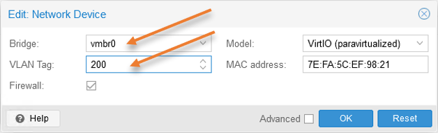

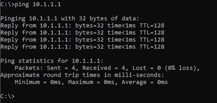
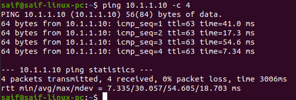
From the virtual machine, you may try to ping the gateway 10.1.1.1 on vlan 200.
As you can see, that worked just fine.
Configure multiple bonds in Proxmox.
Let’s now look at a multiple bond interface configuration instead of one.
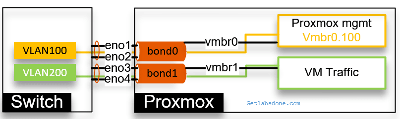
As you can see below, we configured the bond0 with the first two interfaces and bond1 with the second pair of interfaces. Two bridge interfaces are connected to each bonds. Vmbr0 interface is connected to Promox management and vmbr1 is connected to the VM traffic, but for the design to be more affective, you need to start using VLAN on top of it to logically seperate the network.

Both the Proxmox management and the VM traffic are separated using the VLAN. We would only configure the IP address on the Proxmox management interface vmbr0.100.
We would tag the VLAN on the virtual machine itself for the VM traffic as we did before.

Let’s look at the configuration.
Configure the multiple bond interfaces on the Proxmox.
While we have the GUI access, let’s create multiple bond interfaces with VLAN tagged on the Proxmox.
1. Create the first bond interface in Proxmox.
We already have bond0 configured with all the four interfaces, which was easy. Before proceeding with the configuration, you need to identify ports on both the switch and the server.
Since I have a switch stack of two, I take a port from the first switch g1/1 and the second port from the second switch gi2/1 and create bond0, doing the same for bond1.
So when switch 1 goes down, switch2 still provides the connectivity, so there is a redundancy. If you have a similar setup, you might as well reconnect the physical ports accordingly.

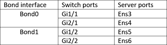
Based on the table above, configure the bond0 and 1 on the server.
We already have bond0 configured, edit the bond0 configuration and remove ens5 and 6 from the list. And click on Ok.

2. Create the bridge interface for bond0.
We don’t have to touch the bridge interface for bond0 for now because we already defined it previously.
Which will take care of the Proxmox management access through bond0.

3. Configure the second bond interface on Proxmox.
Let’s now go ahead and configure the second bond interface for VM traffic.
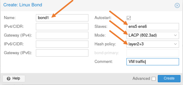
Click on create-> Linux bond.
Name: bond1.
Slaves: Ens5 and 6.
Mode: LACP
Hash Policy: Layer2+3
Add a comment if you like and click on Create.

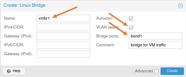
4. Create a bridge interface for bond1.
Click on create-> Linux bridge
In the Linux bridge creatin pop up.
Name: vmbr1
VLAN Aware: Checked.
Bridge ports: bond1.
Add some commands and click on Create.

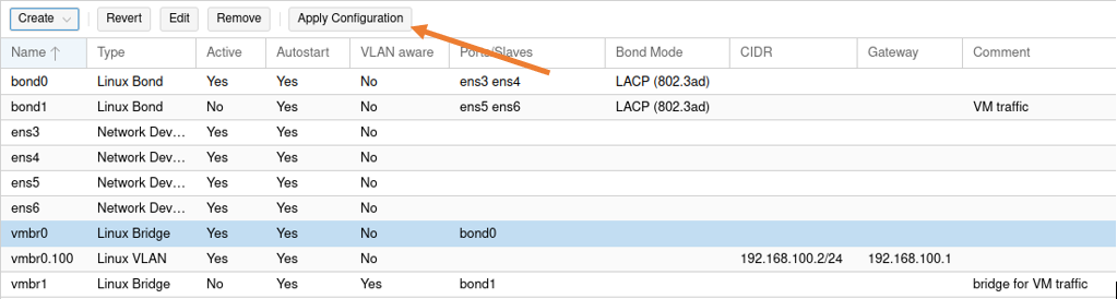
We have now completed the configuration of two bond interfaces, You may apply the configuration,

5. Configure two port-channel on the switch.
For the bond interfaces on the server to work, you need to have an identical configuration on the switch side as well.
Remove the existing port channel.
To remove all the existing port-channel configurations from the switch enter the command below..
Configure terminal
no port1
Change all physical ports on the switch to their default state.
And configure the port-channel as below.
Port-channel 1.
Since port-channel 1 carries Proxmox management traffic, we are tagging the VLAN 100 on it.
Configure terminal
Interface range g1/1, g2/1
switchport trunk allowed vlan 100
 switchport trunk encapsulation dot1q
 switchport mode trunk
 channel-group 1 mode active
Port-channel 2.
And for port-channel 2 we are tagging with VM traffic, which is 200.
Configure terminal
Interface range g1/2, g1/2
switchport trunk allowed vlan 200
 switchport trunk encapsulation dot1q
 switchport mode trunk
 channel-group 2 mode active
You will see two port-channel created, and both the port channel and the VLAN interfaces are up now.
gld-sw-01#sh ip int brief | in Port|Vlan
Port-channel2          unassigned      YES unset  up                    up
Port-channel1          unassigned      YES unset  up                    up
Vlan100                192.168.100.1   YES NVRAM  up                    up
Vlan200                10.1.1.1        YES NVRAM  up                    up
gld-sw-01#
As you can see, two-port channels are now active.
gld-sw-01#show lacp internal
Flags:  S - Device is requesting Slow LACPDUs
        F - Device is requesting Fast LACPDUs
        A - Device is in Active mode       P - Device is in Passive mode

Channel group 1
                            LACP port     Admin     Oper    Port        Port
Port      Flags   State     Priority      Key       Key     Number      State
Gi1/1     SA      bndl      32768         0x1       0x1     0x102       0x3D
Gi2/1     SA      bndl      32768         0x1       0x1     0x202       0x3D

Channel group 2
                            LACP port     Admin     Oper    Port        Port
Port      Flags   State     Priority      Key       Key     Number      State
Gi1/2     SA      bndl      32768         0x2       0x2     0x103       0x3D
Gi2/2     SA      bndl      32768         0x2       0x2     0x203       0x3D
gld-sw-01#
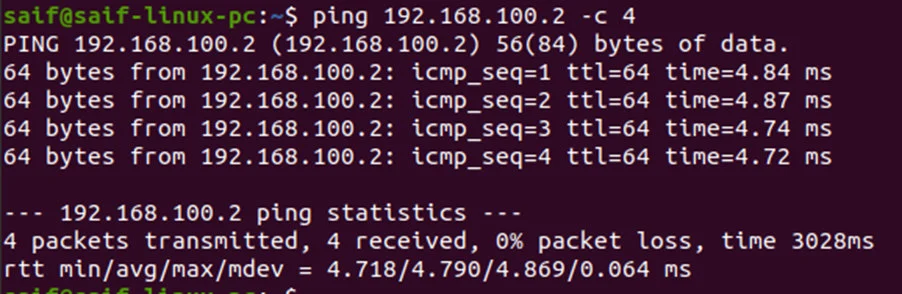
6. Verify the connectivity.
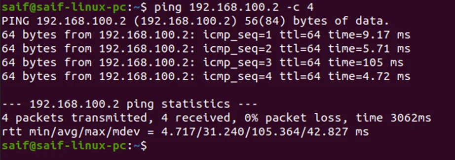
You can now ping from the management PC to the Proxmox IP, and you should get a response.
Note: We already made the management PC as an access port on VLAN 100.
As you can see, I am getting a response.

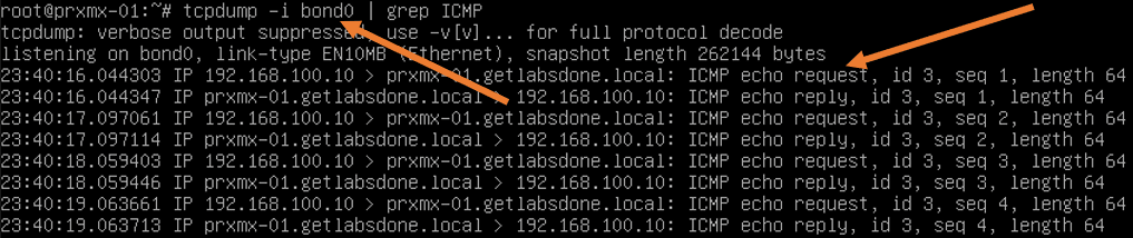
At the same time, I ran quick packet capture on the Proxmox, and as you can see, the ICMP reply and request are going by the bond0 interface.

Attach a VM to the bridge interface vmbr1 and add the VLAN tag as 200.

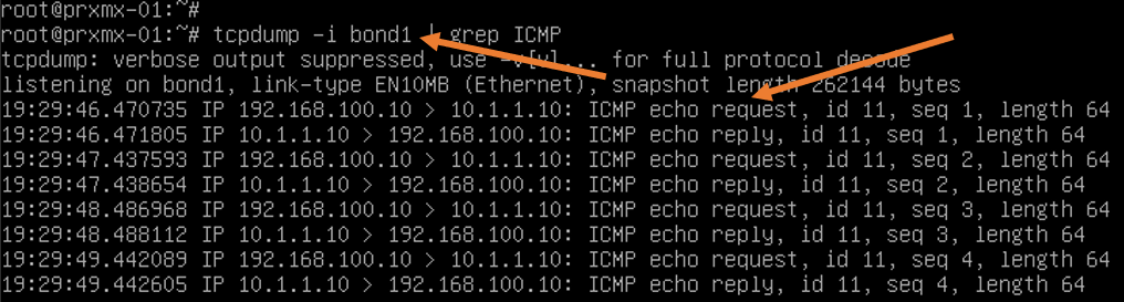
The below packet capture from Proxmox shows the ping packet we just initiated from the management PC, is going via bond1.

Sam
Thursday 10th of October 2024
Hey thanks for this. Found it because it was exactly what I needed to do, and it helped me.
Saifudheen Sidheeq
Thursday 5th of December 2024
You are welcome :) glad it was helpful!