
This is the continuation of the previous article, where we have set up two site-to-site tunnels from AWS to pfSense, as shown below. First being the primary and second being standby. Basically, we have built the transport over which you can now communicate with each side. However, to dynamically send and receive route advertisements and choose the optimal path to the inbound and outbound traffic, we need to use BGP on top of it.
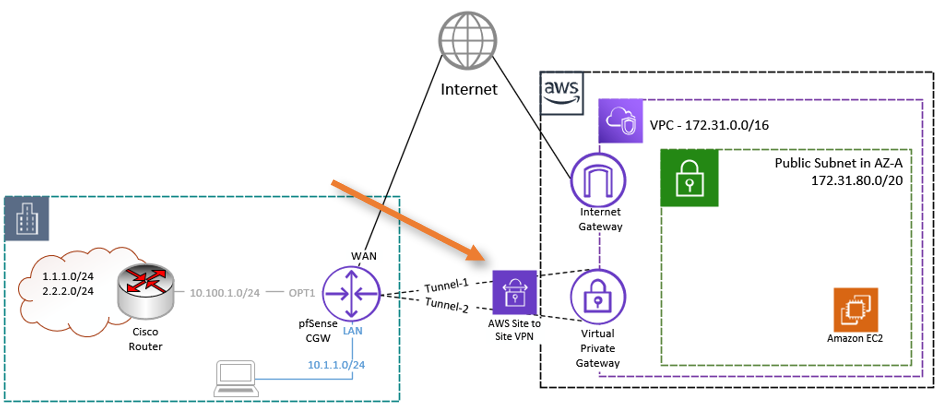
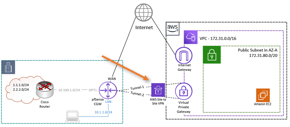
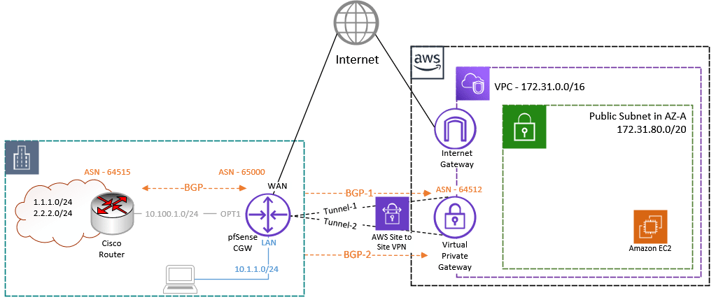
The BGP connection will be between the Pfsense CGW and the AWS site-to-site tunnel, after the tunnel is established it will look like the below.

Note: If you have not set up an AWS site-to-site IPsec tunnel with dynamic routing, please click here to go back to the article. Finish the IPsec tunnel setup and come back here. Only then continue configuring the pfSense with BGP because, as I said, this is the continuation of the previous article.
We selected dynamic routing as the routing mechanism, the appropriate ASN, and route propagation on the VPN gateway while setting the AWS side. On the AWS side, it is the only setting you need to make. If you have experience with networks, you already know how simple the AWS side of configuration is. However, on the remote side, which is where our pfSense firewall is located, we must manually set up everything. So let’s do it right away.
Configure BGP.
We already have a configuration file handy from AWS. In my lab pfSense firewall, I am already running BGP towards one of the cisco routers on the OPT1 interface.
To see the BGP status on pfsense, Goto services-> FRR BGP-> Status.
Currently, we are learning the below routes in the BGP routing table. So after the BGP gets established, you will see those routes propagated to AWS.
Route 10.1.1.0/24 is the LAN route local to the pfSense, and the rest of the routes are learned from the ASN 64515 on the Cisco router.
Having this BGP neighborship from cisco, you will get a clear idea of how the BGP propagation happens. And if you don’t have another BGP peering on pfSense, that’s fine too.
BGP table version is 4, local router ID is 10.100.0.1, vrf id 0
Default local pref 100, local AS 65000
Status codes:  s suppressed, d damped, h history, * valid, > best, = multipath,
               i internal, r RIB-failure, S Stale, R Removed
Nexthop codes: @NNN nexthop's vrf id, < announce-nh-self
Origin codes:  i - IGP, e - EGP, ? - incomplete

   Network          Next Hop            Metric LocPrf Weight Path
*> 1.1.1.0/24       10.100.0.10              0             0 64515 ?
*> 2.2.2.0/24       10.100.0.10              0             0 64515 ?
*> 10.1.1.0/24      0.0.0.0                  0         32768 i
*> 10.100.0.0/24    10.100.0.10              0             0 64515 ?

Displayed  4 routes and 4 total paths
Enable FRR Service.
To configure the BGP on pfSense, you must enable the FRR service.
To enable FRR : Services-> FRR Global/Zebra.
Check the box enable frr, and put some master password.
Configure Route Map.
When you establish the connection between pfSense and AWS, the BGP neighborship will come up; however, you won’t learn any routes on both inbound and outbound. So it is important that you accept the routes from both the inbound and outbound directions.
We are going to accept all the prefixes from both inbound and outbound. Further will call this rout map into the BGP neighborship configuration.
Go back to the Global settings->route-map tab.
Click on Add.
Name: Provide a name For eg: Allow-all.
Action: Permit.
Sequence: 100
In this case, we won’t call any access lists or prefix lists, though you are free to do so if you choose.
Click on Save.
Configure BGP service.
For the BGP configuration, you should start with the ASN, router ID, and the network that you would want to advertise.
Services-> FRR BGP
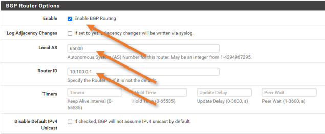
BGP router Options.
Check the Enable BGP routing.
Local AS : 65000
Router ID: not important, but you can put any of the local interfaces IP here.

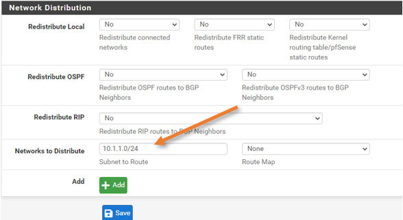
Network Distribution.
We are not redistributing any of the networks. However, we are advertising our LAN network to the BGP. So in the Networks to distribution, enter the subnet and click on Save.

Configure the BGP neighborship towards AWS.
BGP enabled globally on the pfSense firewall in our previous steps, next Let’s configure the bgp neighborship.
BGP Peering towards the first Tunnel.
As we have to configure two tunnels towards AWS, Let’s start with the first Tunnel.
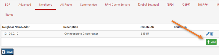
Click on Neighbors.
As you can see, a neighbor is already listed, our cisco router. Depending on your setup, you may or may not have neighborship on the pfSense firewall.
We are going to add two brand new peering from AWS.
Under Neighbors -> Click on Add.

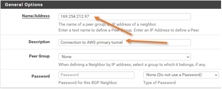
General Options.
Below is the config from the configuration file. Configure the Pfsense side accordingly.
BGP Configuration Options:
– Customer Gateway ASN: 65000
– Virtual Private Gateway ASN: 64512
– Neighbor IP Address: 169.254.212.97
– Neighbor Hold Time: 30
Name/Address: This will be the neighbor’s IP address.
Add some description.

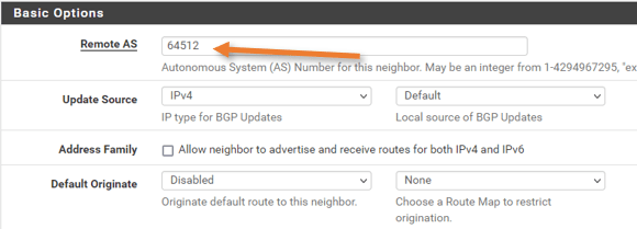
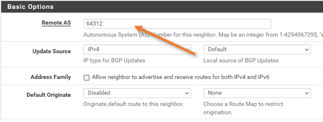
Basic Options.
Remote As : Enter the AWS ASN number.
Update Source: IPv4.

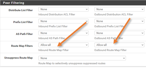
Peer Filtering
choose the route map for inbound and outbound which we created earlier.
And click on Save.
BGP Peering towards Second Tunnel.
We have finished the first BGP peering towards the AWS, Let’s proceed with the second peering.
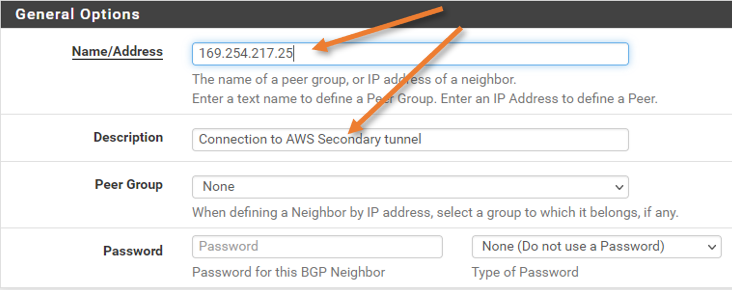
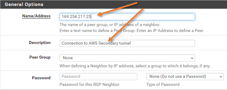
General Options.
Below are the BGP neighborship parameters from the configuration file.
BGP Configuration Options:
– Customer Gateway ASN: 65000
– Virtual Private Gateway ASN: 64512
– Neighbor IP Address: 169.254.217.25
– Neighbor Hold Time: 30
Name/Address: Enter the neighbor’s IP address.
Add some description as well.
Basic options.
Remote as: 64512
Update Source : IPv4 Default.
We are not going to advertise the default route to the AWS. Hence keep the default originate option disabled.

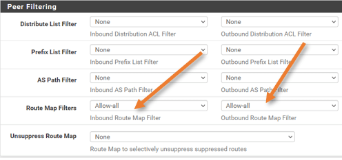
Peer filtering.
This configuration is the same as the first neighbor. Choose the route map we defined to accept the routes from the second neighbor.
Validate the BGP routing between AWS and pfSense.
We have successfully configured the BGP on top IPsec Tunnel towards AWS from PFsense, it is time to test everything and ensure everything is working.
Check the BGP status on pfSense.
To check the BGP status on pfSense, you could goto Status->FRR->BGP
As you can see, there is a new route towards AWS subnet 172.31.0.0 learned from two paths, however, the second path is selected (notice the > symbol)
The second path is selected because of the lower metric of 100, which the AWS automatically injected into the BGP. So, you must leave the local preference and weight to its default value to choose the MED as the BGP attribute.
When the primary path becomes unavailable, the second path will take over.
BGP table version is 17, local router ID is 10.100.0.1, vrf id 0
Default local pref 100, local AS 65000
Status codes:  s suppressed, d damped, h history, * valid, > best, = multipath,
               i internal, r RIB-failure, S Stale, R Removed
Nexthop codes: @NNN nexthop's vrf id, < announce-nh-self
Origin codes:  i - IGP, e - EGP, ? - incomplete

   Network          Next Hop            Metric LocPrf Weight Path
*> 1.1.1.0/24       10.100.0.10              0             0 64515 ?
*> 2.2.2.0/24       10.100.0.10              0             0 64515 ?
*> 10.1.1.0/24      0.0.0.0                  0         32768 i
*> 10.100.0.0/24    10.100.0.10              0             0 64515 ?
*> 172.31.0.0/16    169.254.217.25         100             0 64512 i
*                   169.254.212.97         200             0 64512 i

Displayed  5 routes and 6 total paths
Here is the BGP summary, which shows the list of neighbors.
IPv4 Unicast Summary:
BGP router identifier 10.100.0.1, local AS number 65000 vrf-id 0
BGP table version 17
RIB entries 9, using 1728 bytes of memory
Peers 3, using 43 KiB of memory

Neighbor        V         AS   MsgRcvd   MsgSent   TblVer  InQ OutQ  Up/Down State/PfxRcd   PfxSnt
10.100.0.10     4      64515        71        79        0    0    0 01:01:49            3        5
169.254.212.97  4      64512       138       148        0    0    0 00:00:55            1        5
169.254.217.25  4      64512        93       104        0    0    0 00:00:53            1        5

Total number of neighbors 3
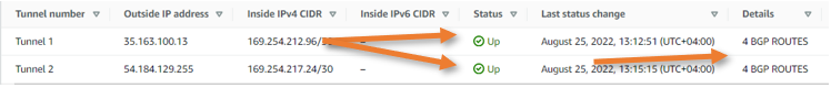
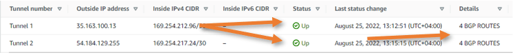
Check the Tunnel and BGP status on AWS.
Similar to how we have checked the BGP status on pfSense, we can also check the BGP status on the AWS side as well.
Goto Site-to-site VPN Connections -> Choose the Tunnel.
As you can see, the Status is up, and under details, we are learning 4 routes.
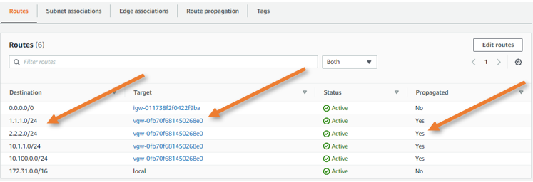
Validate the routes.
In AWS go to VPC->Routing table-> Routes.
You can see all the routes that got propagated from the VPN gateway. As you can infer from the target it says VPN gateway and propagated says yes.

Test the connectivity.
We already have an EC2 instance that we launched in AZ-a, I have logged into it using its public IP.
And when I try to ping the IP 1.1.1.1 and 2.2.2.2 which I configured internally on my network, I can reach just fine.
[ec2-user@ip-172-31-15-103 ~]$ ping 1.1.1.1 -c 2
PING 1.1.1.1 (1.1.1.1) 56(84) bytes of data.
64 bytes from 1.1.1.1: icmp_seq=1 ttl=254 time=297 ms
64 bytes from 1.1.1.1: icmp_seq=2 ttl=254 time=298 ms

--- 1.1.1.1 ping statistics ---
2 packets transmitted, 2 received, 0% packet loss, time 1001ms
rtt min/avg/max/mdev = 297.203/298.025/298.847/0.822 ms

[ec2-user@ip-172-31-15-103 ~]$ ping 2.2.2.2 -c 2
PING 2.2.2.2 (2.2.2.2) 56(84) bytes of data.
64 bytes from 2.2.2.2: icmp_seq=1 ttl=254 time=297 ms
64 bytes from 2.2.2.2: icmp_seq=2 ttl=254 time=298 ms

--- 2.2.2.2 ping statistics ---
2 packets transmitted, 2 received, 0% packet loss, time 1001ms
rtt min/avg/max/mdev = 297.185/297.936/298.687/0.751 ms
And the traceroute shows it is taking the second path.
[ec2-user@ip-172-31-15-103 ~]$ traceroute 1.1.1.1
traceroute to 1.1.1.1 (1.1.1.1), 30 hops max, 60 byte packets
 1  169.254.217.26 (169.254.217.26)  316.828 ms  316.795 ms  316.782 ms
 2  ip-10-100-0-10.us-west-2.compute.internal (10.100.0.10)  316.765 ms  316.687 ms  316.740 ms
[ec2-user@ip-172-31-15-103 ~]$
[ec2-user@ip-172-31-15-103 ~]$ traceroute 2.2.2.2
traceroute to 2.2.2.2 (2.2.2.2), 30 hops max, 60 byte packets
 1  169.254.217.26 (169.254.217.26)  297.759 ms  297.733 ms  303.986 ms
 2  ip-10-100-0-10.us-west-2.compute.internal (10.100.0.10)  301.762 ms  301.832 ms  301.733 ms
Disable the Active Tunnel towards AWS.
To simulate an Outage on the active Tunnel, I have blocked access to the public IP of the AWS tunnel from the on-premise network. The Tunnel went down after a few seconds.
Check the BGP Neighborship table.
As you can see the second BGP neighbor is down and it is in the ‘connect’ state.
IPv4 Unicast Summary:
BGP router identifier 10.100.0.1, local AS number 65000 vrf-id 0
BGP table version 10
RIB entries 9, using 1728 bytes of memory
Peers 3, using 43 KiB of memory

Neighbor        V         AS   MsgRcvd   MsgSent   TblVer  InQ OutQ  Up/Down State/PfxRcd   PfxSnt
10.100.0.10     4      64515        51        54        0    0    0 00:43:08            3        5
169.254.212.97  4      64512        82        84        0    0    0 00:12:25            1        5
169.254.217.25  4      64512        67        72        0    0    0 00:00:29      Connect        0

Total number of neighbors 3
When you check the routing table, you can see it is updated to use a secondary Tunnel to get to the AWS for subnet 172.31.0.0/16.
BGP table version is 10, local router ID is 10.100.0.1, vrf id 0
Default local pref 100, local AS 65000
Status codes:  s suppressed, d damped, h history, * valid, > best, = multipath,
               i internal, r RIB-failure, S Stale, R Removed
Nexthop codes: @NNN nexthop's vrf id, < announce-nh-self
Origin codes:  i - IGP, e - EGP, ? - incomplete

   Network          Next Hop            Metric LocPrf Weight Path
*> 1.1.1.0/24       10.100.0.10              0             0 64515 ?
*> 2.2.2.0/24       10.100.0.10              0             0 64515 ?
*> 10.1.1.0/24      0.0.0.0                  0         32768 i
*> 10.100.0.0/24    10.100.0.10              0             0 64515 ?
*> 172.31.0.0/16    169.254.212.97         100             0 64512 i

Displayed  5 routes and 5 total paths
When you try to traceroute now, you can see it is taking the standby path.
[ec2-user@ip-172-31-15-103 ~]$ traceroute 1.1.1.1
traceroute to 1.1.1.1 (1.1.1.1), 30 hops max, 60 byte packets
 1  169.254.212.98 (169.254.212.98)  365.986 ms  365.913 ms  365.963 ms
 2  ip-10-100-0-10.us-west-2.compute.internal (10.100.0.10)  368.045 ms  370.030 ms  370.101 ms
[ec2-user@ip-172-31-15-103 ~]$
[ec2-user@ip-172-31-15-103 ~]$ traceroute 2.2.2.2
traceroute to 2.2.2.2 (2.2.2.2), 30 hops max, 60 byte packets
 1  169.254.212.98 (169.254.212.98)  297.499 ms  297.491 ms  299.260 ms
 2  ip-10-100-0-10.us-west-2.compute.internal (10.100.0.10)  301.461 ms  301.432 ms  305.726 ms
[ec2-user@ip-172-31-15-103 ~]$
We have successfully deployed the AWS site-to-site IPsec tunnel towards the pfSense firewall using dynamic routing. From the AWS perspective, it provides redundancy. However, when the pfSense firewall goes down, entire site-to-site connectivity goes down. You can set up pfSense in a HA setup which will provide redundancy from the pfSense hardware level. You can also deploy Another site-to-site tunnel from another site that will act as backup. That way, when the primary site-to-site tunnel towards site 1 goes down site 2 will take over the traffic.