
OPNsense is an open-source firewall that you can use in any network out there. If you want to set up OPNsense in your enterprise network, you have a specific commercial gear to choose from, or you want to turn any old PC into a firewall, you could do that as well. Unlike pfsense, you can build a firewall using OPNsense and use it in your commercial network. However, as per pfsense terms of service, you cannot use pfsense firewall on a custom box for commercial use. That is not the case with OPNsense, because of that, many users are moving away from pfsense.
When you build custom hardware, the important challenge that we face is the lack of ports, if it is hardware from a vendor, you will have enough ports to play with, but that’s not the case when you want to turn your old computer as OPNsense firewall.
In this blog, we will build a network using OPNsense firewall with only a single interface by splitting the networks using VLAN’s.
Does VLAN support on OPNsense firewall?
Sometimes when you want to set up a VLAN on the OPNsense, you would realize that none of the interfaces are showing up under VLAN capable interfaces; hence you cannot create the VLAN’s on the OPNsense. We had faced similar issues when using a USB to Ethernet adapter for my network. Later it was found, not all USB to ethernet adapters support VLAN tagging. In this article, you can read more about supported VLAN tagging USB to ethernet adapters. However, pretty much all the ethernet adapters do support VLAN tagging. We have tested with multiple old PCs using both OPNsense and pfsense firewalls, none of which had an issue with creating VLAN.
When creating multiple VLANs on a single interface, you need to ensure that the ethernet interface is at least capable of handling 1Gpbs speed, if you have 10Gbps even better. You can still use the 100Mbps interface for VLANs, and it will still work however you cannot get good throughput with a 100Mbps interface. When tested with the 100Mbps interface with WAN, we got 81Mbps internet speed even though I had 150Mbps internet bandwidth.
So if you are using an old PC with the standard ethernet interface, you should not have any issue; however, if you use a USB to ethernet adapter, you need to be mindful that not all the USB to ethernet support VLAN tagging.
Note: It is not recommended to use a USB to ethernet adapter as a secondary interface for your firewall build. Per my testing, it is not reliable for an extended period of usage.
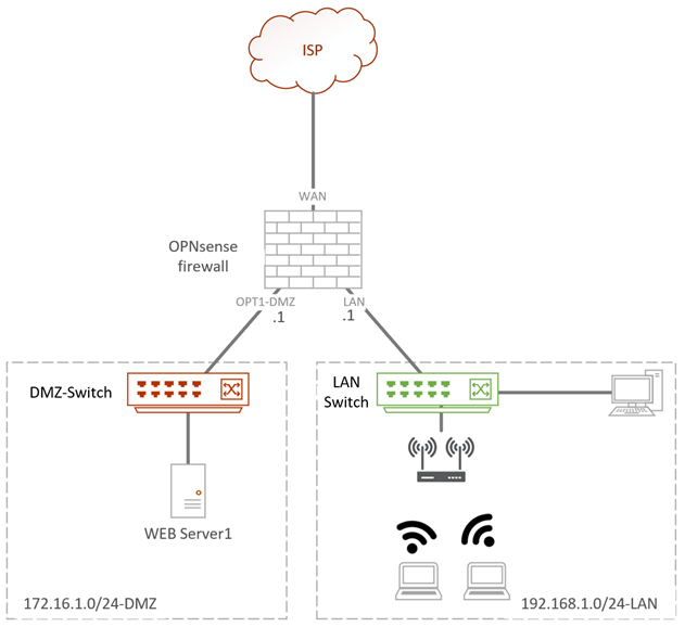
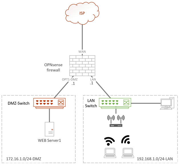
Below is my current topology where I have an OPNsense firewall WAN interface connected to the internet, two switches connected to DMZ, and the LAN interface of the OPNsense firewall.
If we have to build the same network using the VLAN, the diagram will look slightly different.
Below is the same topology with network separates using VLAN.
When the LAN users wanted to go out to the internet, the packet would send to the OPNsense interface with LAN VLAN tagged, and then it is sent to the internet. So let’s see how you can build an OPNsense firewall with VLAN tagged.

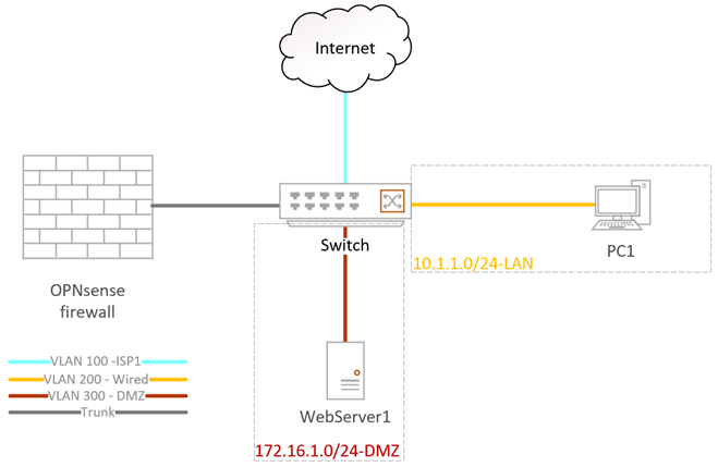
We will use an OPNsense firewall with a single interface where all the LAN, WAN, and the DMZ are separated with VLAN tagged.
When you work with VLAN on an OPNsense firewall, you need to have a Layer2 switch that can carry 802.1q VLAN tagging.
Any switch that can carry 802.1q tagging will work; I am using a cisco switch, and I will also show you how you can configure the same using an Aruba switch.
You don’t need to use the expensive switch, even the less expensive managed switch will work as well, provided it should support 802.1q tagging, so look for that when you make a purchase.
Before we begin, there are a few things to keep in mind. When you want to connect a PC or Server or an end-user machine to a switch, it should configure as an Access port, also known as an untagged port. However, suppose you plan to connect two switches together or to a device that carries multiple VLANs, such as OPNsense firewall. In that case, we need to use a trunk interface that can carry multiple VLANs.
1. Assign the VLAN interface.
- OPNsense single interface connected to the first port on the switch. It will act as a trunk, carrying multiple VLANs on the interface.
- The switch’s second port will connect to the internet on VLAN 100 as an access port. Also, known as an untagged port.
- 3rd port connects to the PC that is on the LAN side on VLAN 200.
- 4th port connects to the server on the DMZ on VLAN 300.
| VLAN | Network | IP Address | Access port (Untagged) | Tagged |
| 100 | ISP | x.x.x.x | Gi0/2 | Gi0/1 |
| 200 | LAN | 10.1.1.0/24 | Gi0/3 | Gi0/1 |
| 300 | DMZ | 172.16.1.0/24 | Gi0/4 | Gi0/1 |
2. Configure the VLAN on the switch.
As I mentioned earlier, I am using a cisco switch and I am also showing the sample configuration from Aruba side, so that you will understand the configuration better.
Power on the switch, console into it, and configure the VLAN as shown below
Note: on both the cisco and Aruba switches VLAN creations are identical.
Switch(config)# configure terminal
Switch(config)#vlan 100
Switch(config-vlan)#name ISP
Switch(config-vlan)#vlan 200
Switch(config-vlan)#name LAN
Switch(config-vlan)#vlan 300
Switch(config-vlan)#name DMZ
Switch(config-vlan)#exit
Switch(config)#exit
Switch#
Configure the Access port Cisco switch.
Follow the below configuration to configure the access port on the cisco switch as per our setup.
cisco-switch(config)# configure terminal
cisco-Switch(config)#interface gigabitEthernet 0/2
cisco-Switch(config-if)#switchport mode access
cisco-Switch(config-if)#switchport access vlan 100
cisco-Switch(config-if)#interface gigabitEthernet 0/3
cisco-Switch(config-if)#switchport mode access
cisco-Switch(config-if)#switchport access vlan 200
cisco-Switch(config-if)#interface gigabitEthernet 0/4
cisco-Switch(config-if)#switchport mode access
cisco-Switch(config-if)#switchport access vlan 300
cisco-Switch(config-if)#exit
cisco-Switch(config)#exit
cisco-Switch#
Configure Access port on Aruba Switch.
Here is the same configuration from the Aruba switch.
Aruba-switch# configure terminal
Aruba-switch(config)# interface 2
Aruba-switch(eth-2)# untagged vlan 100
Aruba-switch(config)# interface 3
Aruba-switch(eth-3)# untagged vlan 200
Aruba-switch(config)# interface 4
Aruba-switch(eth-4)# untagged vlan 300
Aruba-switch(eth-4)# exit
Aruba-switch(config)# exit
Aruba-switch#
Configure trunk interface.
The only interface that carries multiple VLANs is the one that connects to the OPNsense firewall, which is port one on the switch. Let’s go ahead and configure the trunk interface on the switch.
Configure the trunk interface on Cisco.
One important thing to remember when you configure a trunk interface on the Cisco switch is that, by default, it carries all the VLAN’s which is not a good practice; hence I issued a command to remove the VLAN and then added them one by one.
cisco-switch(config)# configure terminal
cisco-switch(config)#interface gigabitEthernet 0/1
cisco-switch(config-if)#switchport mode trunk
cisco-switch(config-if)#switchport trunk allowed vlan none
cisco-switch(config-if)#switchport trunk allowed vlan add 100,200,300
cisco-switch(config-if)#exit
cisco-switch(config)#exit
cisco-switch#
Configure the trunk interface on Aruba.
Configuring the trunk interface on Aruba is far easier. Unlike Cisco, Aruba doesn’t allow all the VLANs on the trunk by default. We have to permit each VLAN one by one, which is a good thing.
Aruba-switch# configure terminal
Aruba-switch(config)# interface 1
Aruba-switch(eth-1)# tagged vlan 100,200,300
Aruba-switch(eth-1)# exit
Aruba-switch(config)# exit
Aruba-switch#
3. Configure the OPNsense VLAN interfaces.
We will now configure the VLAN interfaces on the OPNsense firewall as per our topology. We would require to create 3 VLANs on port1, VLAN 100 for WAN, 200 for LAN, and finally 300 for DMZ.
I am setting up the OPNsense from scratch plugin the port to the first interface of the switch.
I have logged in, and I have the below screen. Since the machine I am working on has only a single interface, it is configured by default as LAN with the IP address 192.168.1.0/24.

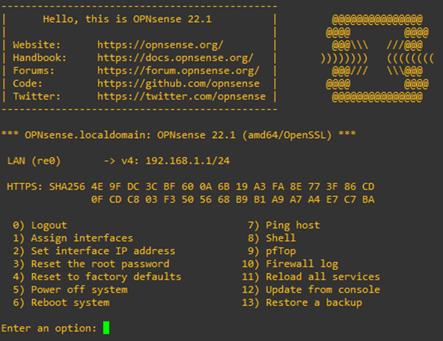
To configure the VLAN interface, press 1- Assign interfaces.
You will be asked if you would like to create a Lagg interface. You can say no to that.
You may say Y for yes on the second prompt for the VLAN configuration.
Enter an option: 1

Do you want to configure LAGGs now? [y/N]: n
Do you want to configure VLANs now? [y/N]: y
And configure the VLAN interface as follows.
VLAN-capable interfaces:

re0      0c:27:74:83:00:00 RealTek 8139C+ 10/100BaseTX

Enter the parent interface name for the new VLAN (or nothing if finished): re0
Enter the VLAN tag (1-4094): 100

VLAN-capable interfaces:

re0      0c:27:74:83:00:00 RealTek 8139C+ 10/100BaseTX

Enter the parent interface name for the new VLAN (or nothing if finished): re0
Enter the VLAN tag (1-4094): 200

VLAN-capable interfaces:

re0      0c:27:74:83:00:00 RealTek 8139C+ 10/100BaseTX

Enter the parent interface name for the new VLAN (or nothing if finished): re0
Enter the VLAN tag (1-4094): 300

VLAN-capable interfaces:

re0      0c:27:74:83:00:00 RealTek 8139C+ 10/100BaseTX

Enter the parent interface name for the new VLAN (or nothing if finished):
After the VLAN configuration completes, you may hit enter. You will now need to map each VLAN interface with the respective network.
After the mapping, you will get the interface assignment view and in the prompt Do you want to proceed? , say Y to that.
Valid interfaces are:

re0              0c:27:74:83:00:00 RealTek 8139C+ 10/100BaseTX
re0_vlan100      00:00:00:00:00:00 VLAN tag 100, parent interface re0
re0_vlan200      00:00:00:00:00:00 VLAN tag 200, parent interface re0
re0_vlan300      00:00:00:00:00:00 VLAN tag 300, parent interface re0

If you do not know the names of your interfaces, you may choose to use
auto-detection. In that case, disconnect all interfaces now before
hitting 'a' to initiate auto detection.

Enter the WAN interface name or 'a' for auto-detection: re0_vlan100

Enter the LAN interface name or 'a' for auto-detection
NOTE: this enables full Firewalling/NAT mode.
(or nothing if finished): re0_vlan200

Enter the Optional interface 1 name or 'a' for auto-detection
(or nothing if finished): re0_vlan300

Enter the Optional interface 2 name or 'a' for auto-detection
(or nothing if finished):

The interfaces will be assigned as follows:

WAN  -> re0_vlan100
LAN  -> re0_vlan200
OPT1 -> re0_vlan300

Do you want to proceed? [y/N]:y
A few seconds later, you will see that OPNsense is configured with LAN and WAN, which is what we expected.
There is no IP address on the WAN because we have not connected the ISP port yet.
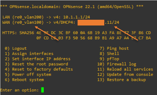
*** OPNsense.localdomain: OPNsense 22.1 (amd64/OpenSSL) ***

 LAN (re0_vlan200) -> v4: 192.168.1.1/24
 WAN (re0_vlan100) ->

 HTTPS: SHA256 4E 9F DC 3C BF 60 0A 6B 19 A3 FA 8E 77 3F 86 CD
               0F CD C8 03 F3 50 56 68 B9 B1 A9 A7 A4 E7 C7 BA

  0) Logout                              7) Ping host
  1) Assign interfaces                   8) Shell
  2) Set interface IP address            9) pfTop
  3) Reset the root password            10) Firewall log
  4) Reset to factory defaults          11) Reload all services
  5) Power off system                   12) Update from console
  6) Reboot system                      13) Restore a backup

Enter an option:
4. Connect a PC into the OPNsense VLAN – LAN interface.
We have configured the LAN interface with VLAN 100 on the OPNsense firewall; let’s go ahead and connect a PC to the port3 of the switch, which is configured as an untagged port for VLAN 100.
As soon as I connected the PC to the switch, I got an IP address from the OPNsense firewall DHCP service.
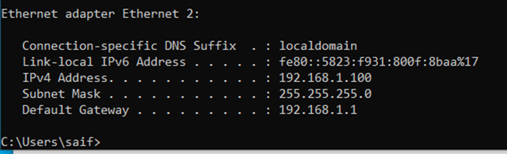

You can now access the OPNsense web GUI using the LAN interface IP, https://192.168.1.1; after you log in, finish the initial setup wizard.
If you are using a private IP address on the WAN side, you need to ensure not to block private network from entering via WAN.
In the LAN configuration, I changed the default subnet to 10.1.1.0/24 network.
5. Connect the WAN interface.
We already configured the WAN interface as VLAN 100; let’s connect the ISP cable to the first switch port configured with the VLAN 100 access port.
Some ISP’s will have their interface configured with VLAN as well. At that time, instead of configuring the ISP port as untagged, you will have to configure them as a trunk and allow the ISP VLAN in it.
In my case, the ISP is not using any VLANs. Hence I can use access port/Untagged port.
As soon as I plugged in the ISP port configured with DHCP, I got an IP address auto-assigned at the WAN side.

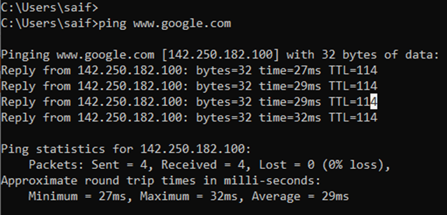
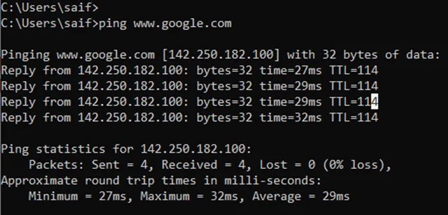
You can observe that the LAN host can now reach the internet, as you can see below, which is cool.
We have now configured a basic OPNsense network with VLAN. Let’s go ahead and add the DMZ now.
6. Configure the DMZ VLAN on fortigate.
Remember in the second step we already defined the 4th interface with VLAN 300, which we will use for the DMZ network. When we added the VLAN 100 and 200, most of the configurations were pretty much automatic. You didn’t have to touch the DHCP service on the LAN side, the WAN side got the IP address automatically from the ISP. A dynamic NAT and security policy were already in place for the LAN users to go to the internet. However, in the case of DMZ, you cannot think by assigning the port to DMZ, everything will work automatically. We have to configure everything manually.
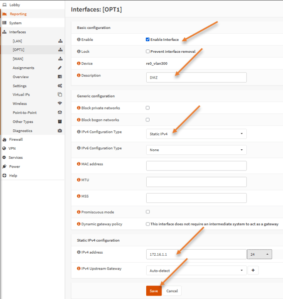
To configure the DMZ network in OPNsense, goto Interfaces-> OPT1
- Check enable interface.
- Rename the Description from OPT1 to DMZ.
- Choose IPv4 configuration type to Static IPv4.
- Static IPv4 configuration.
- Ipv4 address: 172.16.1.1/24
- Click on Save and apply changes.

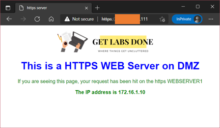
I have already configured the static one-to-one NAT and security policy to access the DMZ server from the internet. Follow the article here to learn more about setting up OPNsense DMZ.
And as you can see, I can access my DMZ server just fine from the internet.

Conclusion :
It is not recommended to use all the services in a single interface using the VLAN on a bigger network, but if you don’t have an option to add a secondary interface, the VLAN is the only way to go. I have not noticed any issues using the VLAN on a single interface. Hopefully, by now you must have understood which port needs to be configured as accessport and the trunk port when it comes to VLAN and how to bring the OPNsense network online with VLAN.