
You got a palo alto firewall at the edge of your branch network and the headquarters, and you are planning to run IPsec with a dynamic routing protocol on top of it. But you are confused with all the IPsec and BGP configurations, even if you get everything up and running how do you manage it properly for the traffic.
In this blog article, we are going to deploy a palo alto firewall site to site vpn between two sites and run bgp on top of it.
Below is the topology that I am working on, I have headquarters in California with the subnet 10.1.0.0/16, we are now going to connect to a remote branch which is in Bangalore has a subnet of 10.2.0.0/16.
Since California is the main hub, we would be using dual ISPs and bangalore being a small branch it has only a single ISP.
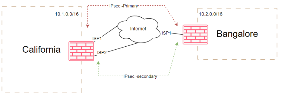
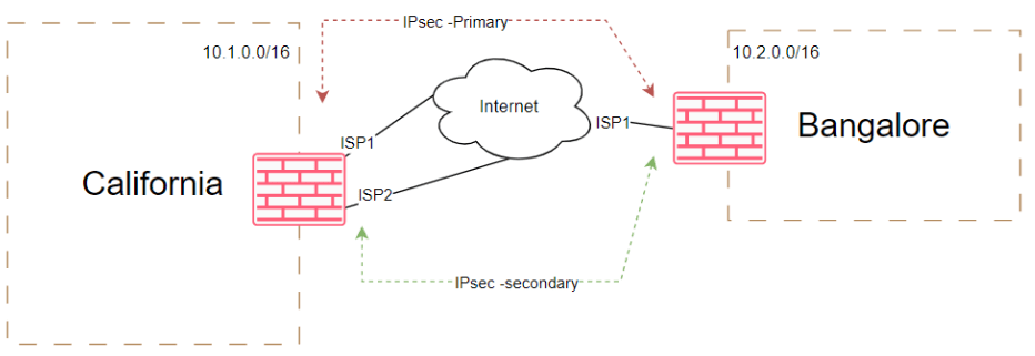
Using this internet as transport, we are going to build two IPsec tunnels on top of it, which provide redundancy and avaialability of the tunnels.
Tunnel Architecture and Redundancy
To provide robust connectivity, we will establish two IPsec tunnels over the internet transport. This approach offers redundancy and high availability for our network connections. The architecture of the tunnels will be as follows:
Primary IPsec Tunnel: The primary IPsec tunnel will connect California ISP1 to Bangalore ISP1. It serves as the primary path for inbound and outbound traffic using BGP, ensuring efficient routing and optimal performance.
Secondary IPsec Tunnel: The secondary IPsec tunnel connects California ISP2 to Bangalore ISP1, serving as a backup link in case of primary tunnel failure. This redundancy ensures uninterrupted connectivity and minimizes disruptions. While additional ISPs in Bangalore can enhance resilience, this lab will focus on a single ISP in Bangalore for simplicity and clarity.
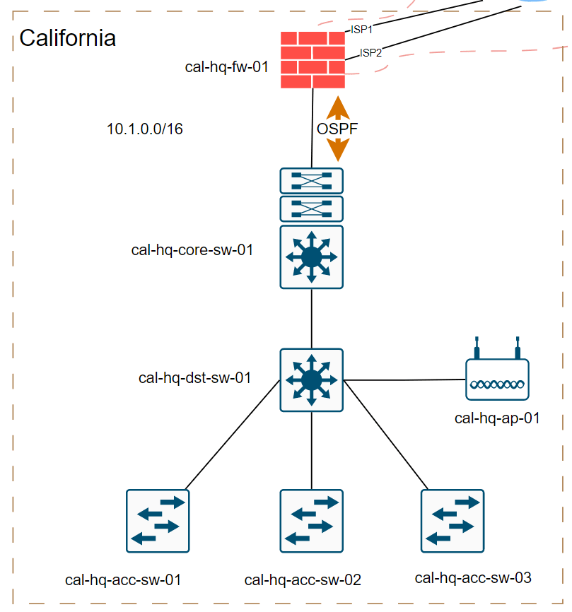
Routing protocol: As you can see below, the firewall further connected to a core switch and to make this lab interesting, the routing between the palo alto firewall and the internal core switch uses OSPF as the internal routing protocol.
However, for the IPsec tunnel traffic we are going to use BGP (EBGP), Which means, to make the routes avaiable at each remote ends, we have to redistribute the ospf into the BGP.
As a result, when we look at the routing table at both sides after the tunnel and everything is built, we should be able to see all the internal routes from both ends.

In this blog, we will be covering the setup of IPsec and BGP. However, going into both topics in a single article would be overwhelming. Therefore, we will focus on the IPsec tunnel configuration in this blog post, while the next article here (Part 2) will cover the BGP configuration.
So this is part 1 of the configuration.
Before we begin, we already have ISP configuration and internal routing taken care of and here is the current interface information from both the locations.
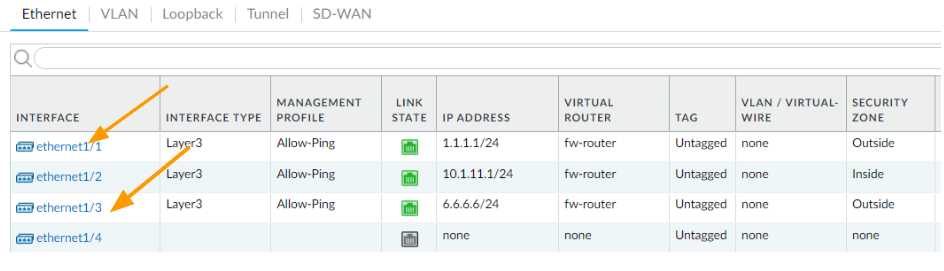
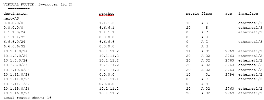
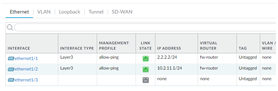
California
As you can see, I have an inside interface, which has an IP of 10.1.11.1 as the gateway and I have two ISPs connected to the outside interface ethernet1/1 and ethernet1/3 respectively.

And here is the route table from the firewall, as you can see, it has only the internal routes and the default routes towards two ISP’s where the ethernet1/1 is the preferred route over ethernet1/3 as it has a higher metric.

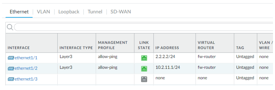
Bangalore
In bangalore, we have single ISP, and just like california, we too have inside interface configured as 10.2.11.1/24
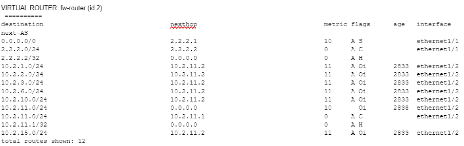
And here is the current routing table.
We have a single default route towards the internet, and the rest of the route is from inside which falls under the same 10.2.0.0/16 subnet.

Lets now go ahead and build the IPsec tunnel starting from California.
1. Gather the IPsec parameters.
When you build the IPsec tunnel, it is important that you collect the required details from the remote side that you are going to connect to.
Sometimes it might be a third party vendor, so we cannot blindly go ahead and configure the tunnel, we will need to collect the information first and then configure the IPsec tunnel.
Here is the information that we are going to use to set up the tunnel.
California.
The first thing is the public IP address of the tunnel, so when you set up the tunnel, you need to make sure to change it according to your setup.
| Local IP | peerIP | |
| IPsec primary | 1.1.1.1 | 2.2.2.2 |
| IPsec secondary | 6.6.6.6 | 2.2.2.2 |
Bangalore
The Bangalore IP address would be right opposite of california.
| Local IP | peerIP | |
| IPsec primary | 2.2.2.2 | 1.1.1.1 |
| IPsec secondary | 2.2.2.2 | 6.6.6.6 |
Phase 1 parameters for both sides.
When you build the tunnel it is important that you set the phase 1 parameters, though paloalto do provide default parameters, we are going to use the below parameters for the tunnel setup.
| DH Group | Authentication | Encryption | Key Lifetime | |
| IKE Crypto | group2 | sha256 | aes-256-cbc | 8Hours |
Phase2 parameters
Same goes for phase 2 parameters as well.
| DH Group | Authentication | Encryption | Lifetime | |
| IPsec Crypto | group2 | sha256 | aes-192-cbc | 1hour |
2. Configure the headquarters IPsec tunnel (California)
The IPsec tunnel creation consists of phase 1 and phase 2. Let’s go ahead and configure phase1 of the tunnel in California and then we would configure phase2.
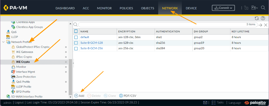
Configure IKE crypto
Open palo alto firewall and then go to Network – Network Profiles – IKE crypto
Click on Add, you could even use the predefined IKE-cryptos from palo alto, however as I mentioned we are going to use different parameters, as per our gathered information.

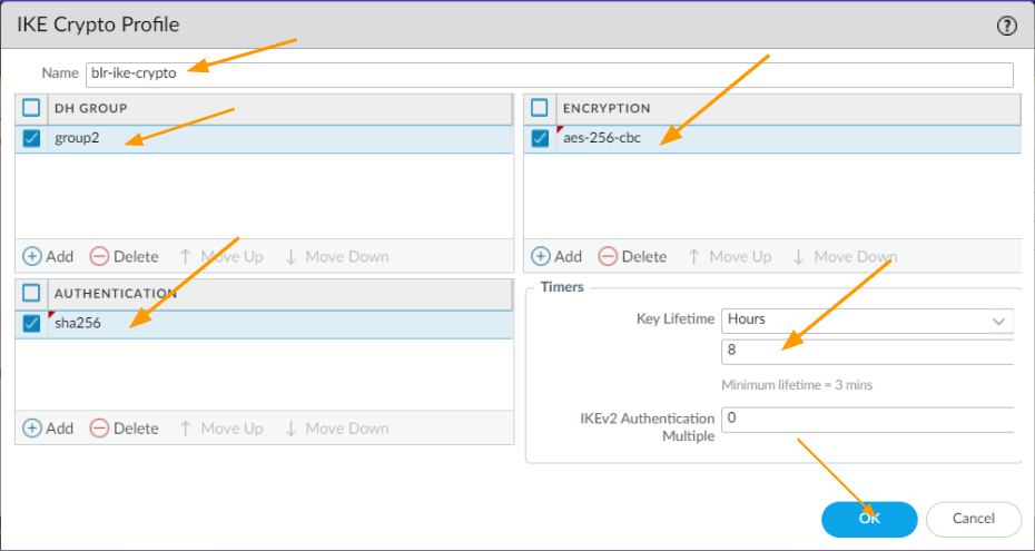
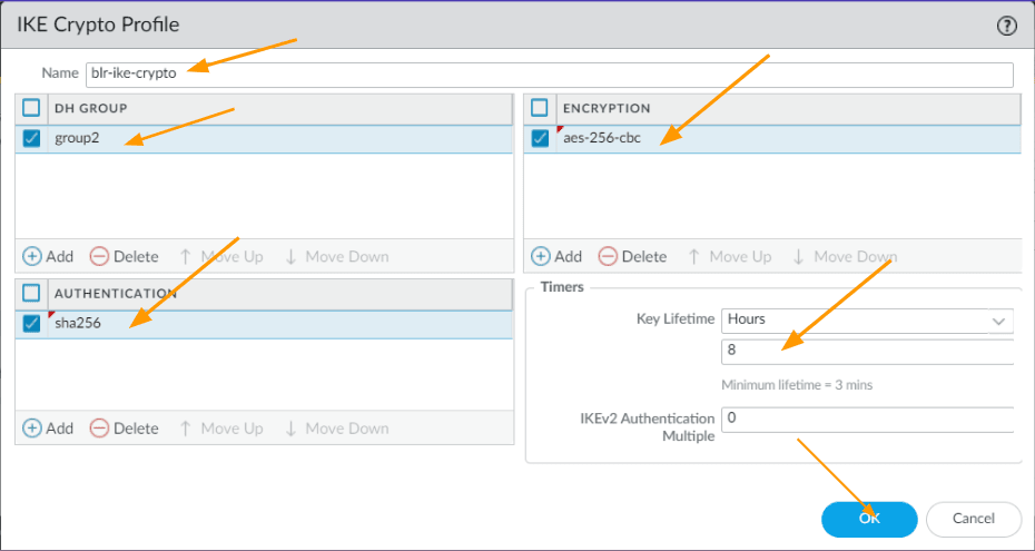
- Name: blr-ike-crypto
- DH Group: group2 as per our sheet.
- Encryption: aes-256-cbc
- Authentication: sha256
- Timers: Key lifetime- 8 hours
And Click on ok.
Configure IPsec crypto
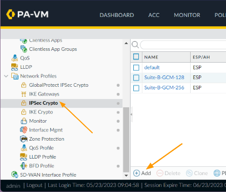
After the IKE crypto, lets now go ahead and configure the IPsec crypto, click on IPsec crypto on the left pane.
Click on Add.
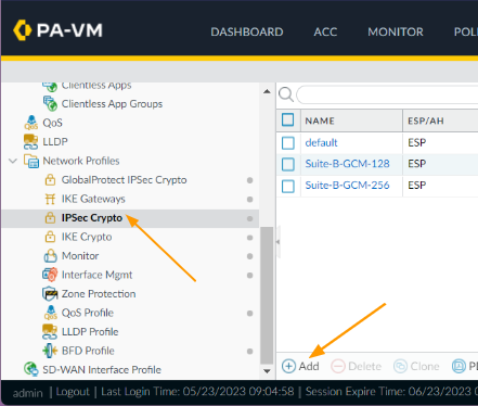
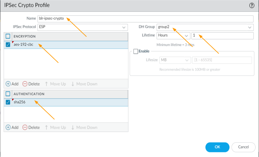
Here again, we are going to use brand new IPsec crypto as per our requirement.
- Name: Enter user friendly name.
- Encryption: aes-192-cbc
- Authentication: sha256
- DH group: group2
- Lifetime: 1 hour
Click on Ok.

Configure primary IKE gateway.
Lets now configure the primary IKE gateway from the ISP1, this is where you mention the public IP address of the IPsec tunnels.
- Name: Enter some name.
- Version: IKEv2 preferred mode
- Address type: IPv4
- Interface: ethernet1/1 (you need to choose your outside interface)
- Local IP address: 1.1.1.1/24
- Peer IP address Type: IP
- Peer ip Address: 2.2.2.2
- Authentication: pre-shared key
Enter the pre-shared key that you are going to use on both ends, you need to ensure that both sides match.
And Click on Ok.


Note: In case, if you are using the palo alto firewall behind a NAT device, then you need to enable NAT traversal by going into Advanced options, but in our case, it is okay to leave as it is as the public IP address configured on the outside interface.
Configure Secondary IKE gateway.
Just like the primary gateway, we would now configure the second IKE gateway which we will use it for secondary tunnel.
- Name: Enter name.
- Version: IKEv2 preferred mode
- Address type: IPv4
- Interface: ethernet1/3 (you need to choose your outside interface)
- Local IP address: 6.6.6.6/24
- Peer IP address Type: IP
- Peer ip Address: 2.2.2.2
- Authentication: pre-shared key
Enter the pre-shared key and Click on Ok

Create primary tunnel interface.
Finally create the tunnel interface, which will also act as BGP interface for the IPsec tunnels, so we need to also configure an IP address.
So I am going to use the link-local address 169.254.1.0/30 for the first tunnel and 169.254.2.0/30 for the second tunnel.
Click on Interfaces-> tunnel
Click on Add.
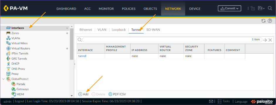

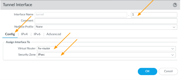
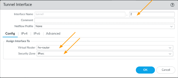
- Interface name: enter 1, it will be tunnel.1
- Config:
- Virtual router: choose the firewall router
- Security zone: I am choosing IPsec as the zone, if you dont have one, you may go ahead and create one.
- Config:

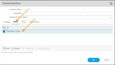
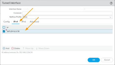
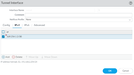
Click on the IPv4 tab, and then configure the link local address which we will use for the BGP neighborship.
In my case 169.254.1.1/30

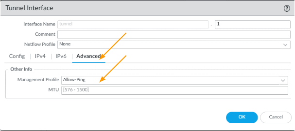
Though it is not needed, I am also enabling ICMP ping by going into Advanced and then choosing a management profile with ping enabled, because you might need to troubleshoot the tunnel later on and click on Ok.

Create Secondary tunnel interface.
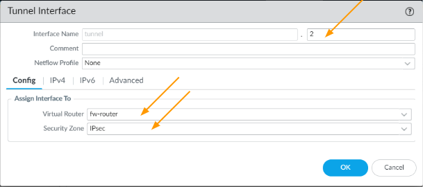
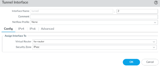
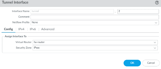
Similar to tunnel1 we are going to add tunnel 2, click on add.
- Interface name: 2, it will be tunnel.2
- Config:
- Virtual router: fw-router
- Security zone: IPsec
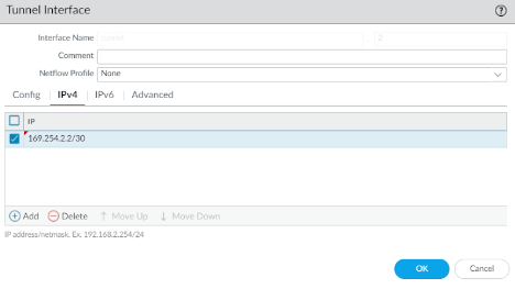
- Click on IPv4.
Enter the link local address here and click on Ok.

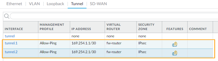
You can now see, there are two tunnel interfaces created.

Build the IPsec tunnel.
With all the information we configured, we are ready to configure the IPsec tunnel in palo alto.
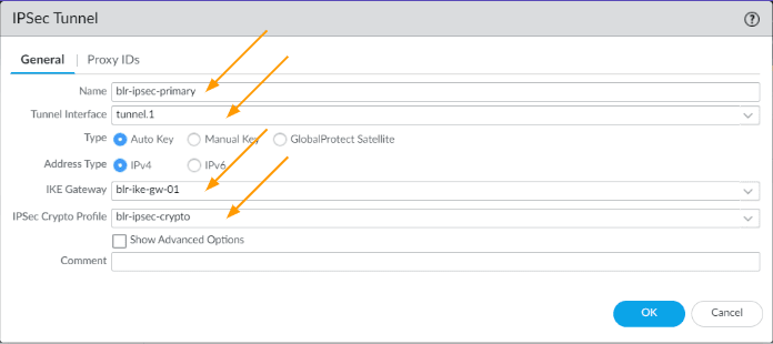
Setup primary IPsec Tunnel.
Click on IPsec tunnels from the left pane.
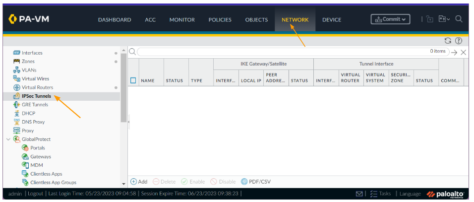

Click on Add,
- Name: blr-IPsec-primary
- Tunnel interface: Tunnel.1
- IKE Gateway: choose the IKE gateway for primary tunnel
- IPsec crypto profile: choose the crypto profile as well and Click on OK.

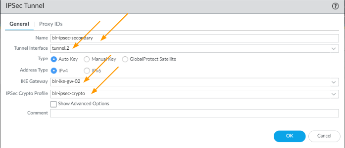
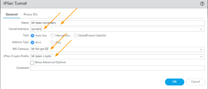
Setup Secondary IPsec tunnel.
Click on add again to add the secondary IPsec tunnel.
- Name: blr-IPsec-secondary
- Tunnel interface: Tunnel.2
- IKE Gateway: choose the IKE gateway for primary tunnel
- IPsec crypto profile: choose the crypto profile as well and Click on OK.
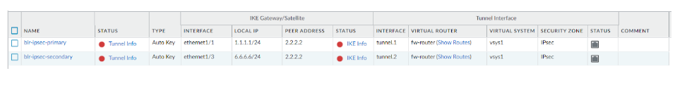
As you can see, there are two tunnels now created, however it is down at the moment, because we have not configured the remote end.
In order for the tunnel to come up, you not only setup the tunnel on the remote end, but also some traffic has to initiate through the tunnel. but we can bring up the tunnel to ensure both the phase1 and phase 2 come up later on using the CLI.

3. Create security policy for the IPsec traffic at HQ.
The whole point of enabling IPsec is to establish the connectivity between two sites, and building the IPsec with routing isn’t enough.
As a firewall, all the traffic that is going in and out of the tunnel will be blocked by default.
You need to open the door for the traffic to come and go.
For that you need to create something called security policies.
We are going to add two policies.
Add the first policy.
Click on policies -> Security.
Click on Add.
First we will add the policy to allow the traffic from california to Bangalore.
- General:
- Name: Allow-traffic-to-blr
- Source:
- Source Zone: Inside
- Source Address: 10.1.0.0/16
- Destination:
- Destination Zone: IPsec
- Destination Address: 10.2.0.0/16
- Actions: Allow and click on Ok.
Add a second policy.
- General:
- Name: Allow-traffic-from-blr
- Source:
- Source Zone: IPsec
- Source Address: 10.2.0.0/16
- Destination:
- Destination Zone: Inside
- Destination Address: 10.1.0.0/16
- Actions: Allow and Click on Ok.
So let’s go ahead and commit the changes we have done so far on the california site.
4. Configure the remote tunnel (Bangalore)
We have configured the head quarter side, let’s now move on to a remote branch site which is bangalore.
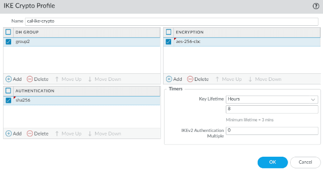
Configure IKE crypto.
Login to the firewall and then goto Network -> Network profiles-> IKE-crypto
Click on Add
- Name: cal-ike-crypto
- DH Group: group2
- Encryption: aes-256-cbc
- Authentication: sha256
- Key lifetime: 8 hours
Click on Ok.

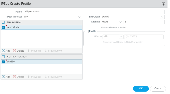
Configure IPsec crypto.
Next click on IPsec crypto and add the details as follows.
- Name: cal-IPsec-crypto
- IPsec protocol: Esp
- encryption: aes-192-cbc
- Authentication: sha256
- DH Group: group2
- Lifetime: 1 hour
Click on Ok.

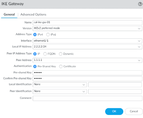
Configure the IKE gateway.
- Name: cal-ike-gw-01
- Version: IKEv2 preferred mode
- Interface: ethernet1/1
- Local IP address: 2.2.2.2
- Peer IP address Type:IP
- Peer Address: 2.2.2.2/24
- Pre-shared key: Enter the pre-shared key that is matching with the headquarters.
And then Click on Ok.


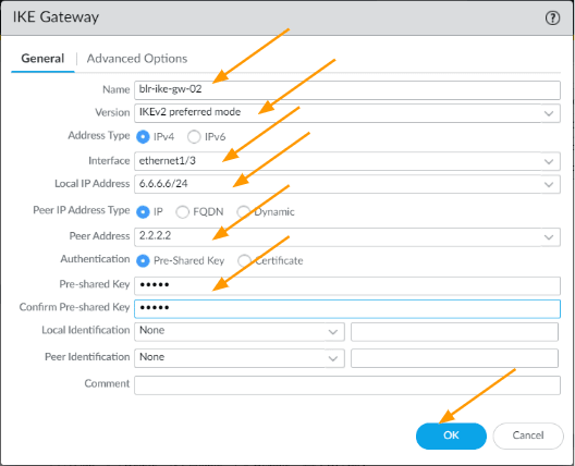
Same way set the parameters for the secondary tunnel.
- Name: cal-ike-gw-02
- Version: IKEv2 preferred mode.
- Address type: IPv4
- Interface: ethernet1/1
- Local IP address: 2.2.2.2/24
- Peer IP address Type: IP
- Peer Address: 6.6.6.6
- Authentication: pre-shared key
- Pre-shared key: enter the preshared key and confirm the same and then click on Ok.

Primary tunnel interface creation
Goto interface, and tunnel.
Click on Add to create a new tunnel interface.
- Interface name: 1
- Virtual router: your firewall router
- Security zone: IPsec
Click on IPv4
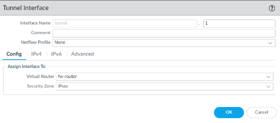

Add the link local address for the primary tunnel.
We used 169.254.1.1 in the headquarters primary tunnel so here we need to add the second IP which is.
169.254.1.2/30

Secondary tunnel interface creation
Same config for the second tunnel as well, except the IP address.
Choose the virtual router and the zone.
Click on IPv4 tab
Add the IP address 169.254.2.2/30 which is the second IP address.

Setup IPsec tunnel in bangalore
Goto IPsec tunnels on the left pane, and combine all the changes into one and create two Ip sec tunnels.
Click on add.
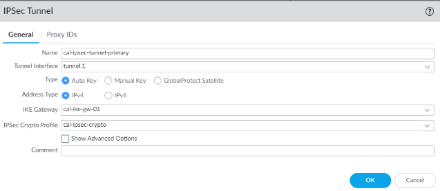
General:
- Name: cal-IPsec-tunnel-primary
- Tunnel interface: choose the first interface.
- Address Type: IPv4
- IKE Gateway: Choose the first gateway.
- IPsec crypto profile: choose the IPsec crypto profile we created.
Click on Ok.

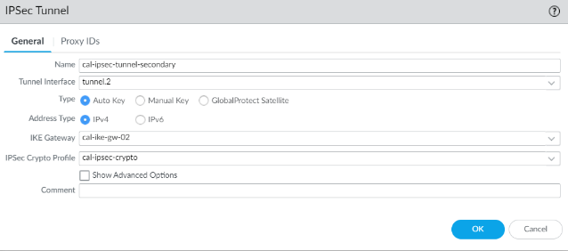
Same way add the secondary tunnel as well.
- Name: cal-IPsec-tunnel-secondary
- Tunnel interface: choose the second tunnel interface
- Address type: IPv4
- IKE gateway: choose the second gateway.
Choose the IPsec crypto profile as well.

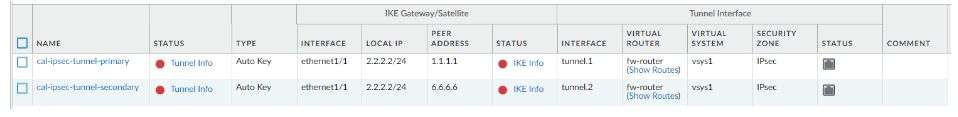
You can see, both the primary and secondary tunnels are created and it shows down, also the status shows grey.

5. Configure the security policy.
Add first policy.
Click on policies -> Security.
Click on Add.
First we will add the policy to allow the traffic from california to Bangalore.
- General:
- Name: Allow-traffic-to-cal
- Source:
- Source Zone: Inside
- Source Address: 10.2.0.0/16
- Destination:
- Destination Zone: IPsec
- Destination Address: 10.1.0.0/16
- Actions: Allow and click on Ok.
Add second policy.
- General:
- Name: Allow-traffic-from-cal
- Source:
- Source Zone: IPsec
- Source Address: 10.1.0.0/16
- Destination:
- Destination Zone: Inside
- Destination Address: 10.2.0.0/16
- Actions: Allow and click on Ok.
We have configured ipsec tunnels and its required changes, lets go ahead and commit changes.
6. Test the IPsec tunnel connectivity.
After the commit the tunnel still will not come up, because there is no traffic passing through it and moreover for the traffic to go through the tunnel there should be some routes configured, which is not there either.
To bring up the tunnel for testing you can login to the cli of the california firewall and enter the command below.
test vpn tunnel ike-sa gateway <tunnel name>Note: This is just a test to see, whether the ipsec tunnel phase1 and phase2 is working or not, in order to send the actual traffic, you need to have routing enabled and configured, which we will do next.
admin@cal-hq-fw-01> test vpn ike-sa gateway blr-ike-gw-01

Start time: May.25 14:19:50
Initiate 1 IKE SA.

admin@cal-hq-fw-01> test vpn ike-sa gateway blr-ike-gw-02

Start time: May.25 14:19:52
Initiate 1 IKE SA.

admin@cal-hq-fw-01>
You can now go back to the GUI and see the tunnel interface is now up, showing the green indicator.
California side


Bangalore side


The both side green indicates that the IP is now completely up and ready to send traffic, however though the tunnel interface is up, you cannot really send any traffic through this tunnel, for that we need to configure routing, which we have covered in this blog article.