
As you know if you wanted to get hands-on and practice the Palo alto firewalls, the best place is to virtualize them. As many of you out there may not have the options to set up a physical lab. However, there are alternate ways to spin up the Palo alto lab in the cloud using AWS, but that again will incur a cost when you use the compute resources.
So, it is better to virtualize them on your local environment to practice the lab. I have covered, how you can setup a Palo alto lab in gns3, also allow the end-user machine to the internet in my previous posts.
Can I install Palo alto in VMware workstation?
If you have decent computer configuration, you can setup Palo alto firewall in VMware workstation.
In this blog, we are going to install Palo alto firewall in VMware workstation. Post which we would configure NAT and security policies, and DHCP services in the Palo alto firewall. Finally, test the connectivity using the end-user hosts.
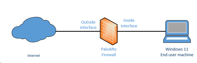
And here is the topology that we are going to build.

Prerequisite.
- Download Palo alto ova image.
I am using PA-VM-ESX-10.1.0. You need to have a partner account to download the Palo alto ova image from the Palo alto web portal. If you don’t have one, google will be your best friend
- VMware workstation pro
In this lab we are using VMware workstation 16 and any older versions of VMware workstation will work as well. You can get a VMware workstation here.
Steps to configure palo alto firewall on VMware.
- Setup the VMware network for Palo Alto.
- Configure Palo alto in VMware workstation.
- Configure the Palo alto interface in VMware workstation.
- log in to the VM and Verify the Palo Alto management network.
- Access the Paloalto web GUI.
- Interface Management profile creation.
- Palo alto Firewall Zone creation.
- Create the outside interface.
- Validate the outside interface.
- Verify the ICMP traffic.
- Configure the inside interface.
- Configure the LAN users to access the internet.
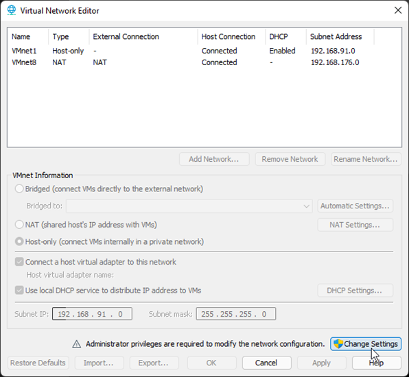
1. Setup the VMware network for Palo Alto.
We would require three network interfaces to start the lab. By default, you may only have three interfaces on the VMware workstation (Vmnet0, Vmnet1, and VMnet8) under virtual adapter settings. However, we are going to use VMnet2, VMnet0, and VMnet1.
Note: You need to click on Change settings on the virtual Network editor, to see all the default interfaces.
Click on Edit and virtual adapter settings.

1st interface – Management interface – will use VMnet2. We do not have VMnet2 in the list, so click on Add network.
- On the Add a Virtual Network pop up choose the VMnet2 and click on OK.
2nd interface – Outside (Untrusted) interface connected to the internet – Will use VMnet0 (Bridged) interface.
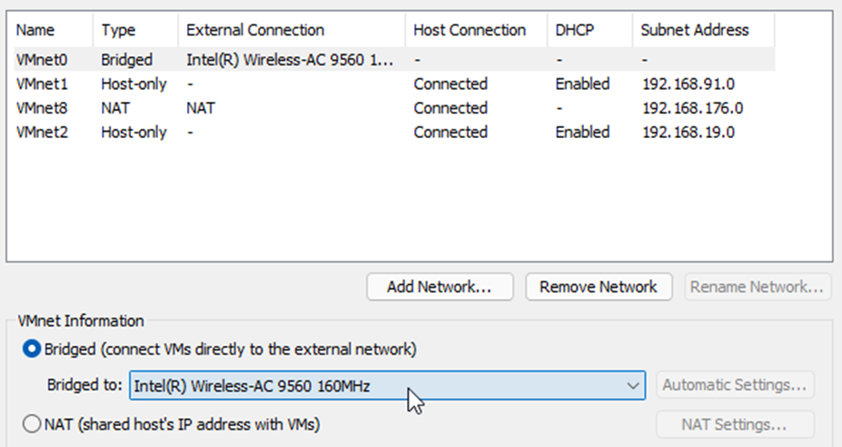

Note: Make sure The Bridge to the interface is your local area network interface adapter connected to the internet. In my case, it is the wifi adapter. If you have connected via wired, it will be an ethernet interface.
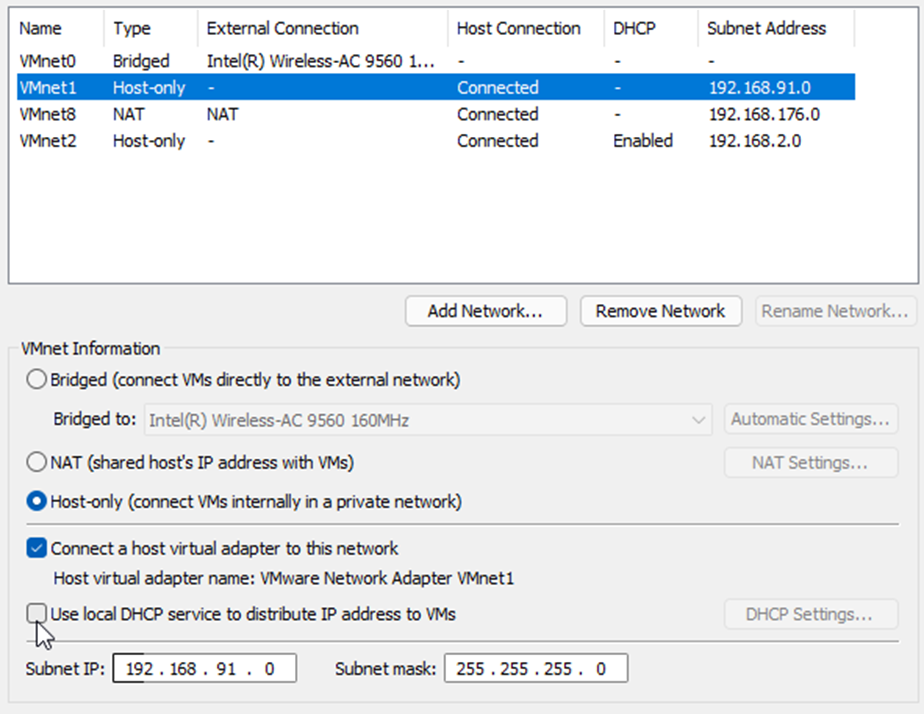
3rd interface – inside interface – we will use VMnet1 (Host-only) for this purpose. We need to disable DHCP for this interface.
Choose the VMnet1 – Uncheck the option that says Use Local DHCP service to distribute IP address to VMs.

2. Configure Palo alto in VMware workstation.
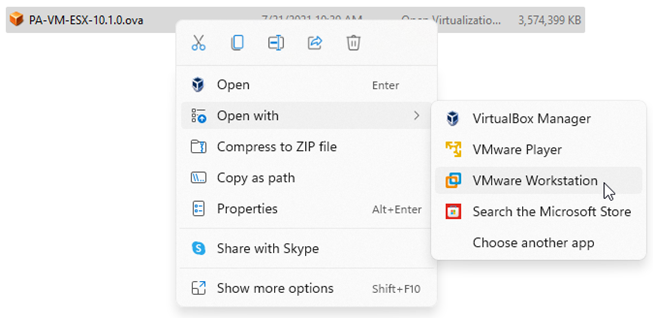
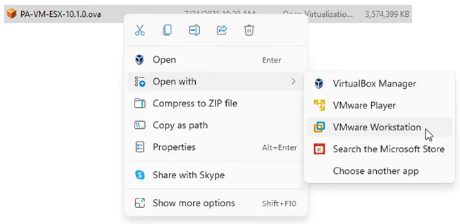
After the VMware network configuration part is completed, you need to import the Paloalto VM appliance into the VMware workstation.
- Go back to the file that you have downloaded. And open the OVA file in VMware workstation. This process will start the Paloalto VM import.
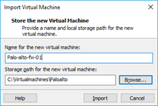
- You will be asked to name the VM and choose the storage for the VM.
Name the firewall according to your lab setup, I am using Palo-alto-fw-01 and the path I changed to the custom location. You may leave the default if needed.

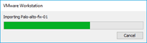
The VM import now begins, and it will take a few minutes to complete.

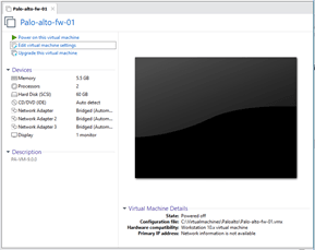
Once completed you should be able to see the VM properties, as you can see below though we didn’t configure the VM resources, it is picked up by the VM automatically.

3. Configure the Palo alto interface in VMware workstation.
The Palo alto VM picked up the memory as 5.5GB, you may reduce it if you would like, the 4GB is the minimum recommended by the Palo Alto.
It also picked up the 3 network interfaces, we need to make some changes on that according to our lab. So click on Edit virtual machine settings on the top, a new pop up window will open.
All the three interfaces have been configured to use bridged interface by default, but we are not going to use the bridged interface rather we will use the custom adapter which we have set up initially.
Before.
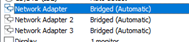
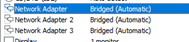
After
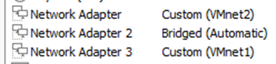
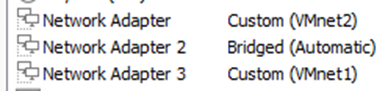
We have configured the network as per our network configuration, you may click on Ok now.
Let’s go ahead and power on the Virtual machine by clicking power on the virtual machine.
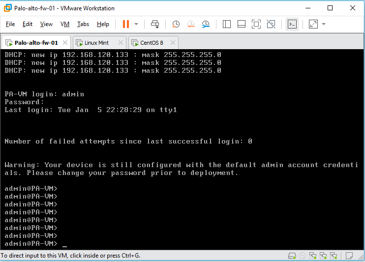
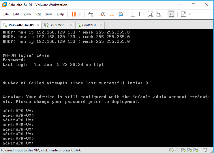
4. log in to the VM and Verify the Palo Alto management network.
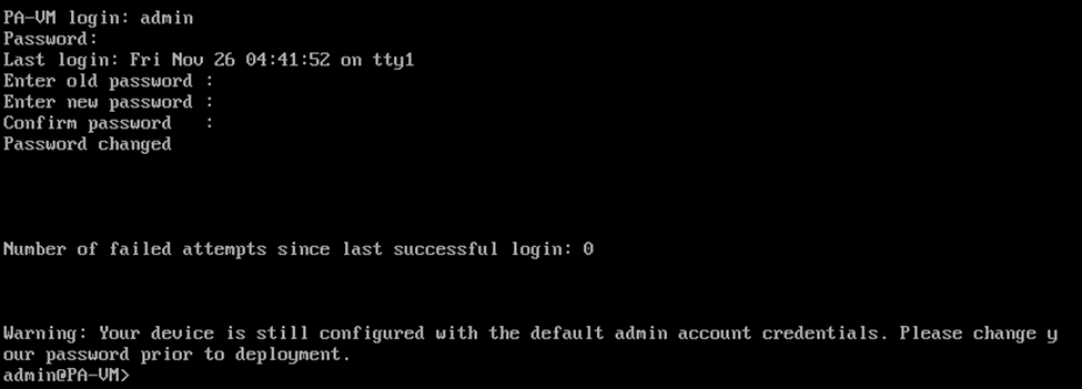
It will take some time for the VM to load, just give it about 5mins for the VM to load properly. During this time, when you get a prompt to enter the credentials you won’t be able to login, as it would say the credentials are incorrect.
You will have to wait to see the login prompt as PA-VM login:
The default credentials are
Username: admin
Password: admin
As soon as you enter the credentials, it will ask you to reset the password for the admin account.

If you have followed the steps till this point, your Paloalto VM will be configured with the management interface with the DHCP IP address. Type show interface management to see the management IP configuration.
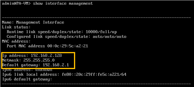

As you can see the management IP is configured with a DHCP IP address, lets try to ping the management default gateway to see whether you are able to reach the gateway or not.
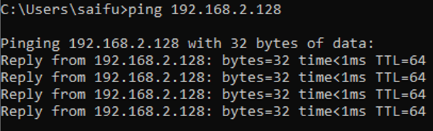
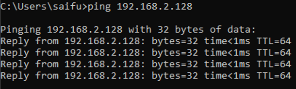
Awesome! we are able to reach the default gateway which means you should now be able to access the Paloalto gui from your local machine.
In case if you are planning to use a Static IP address for management purpose, then you can follow the guide here and come back.
5. Access the Paloalto web GUI.
We have successfully configured the Paloalto management interface in the VMware workstation.
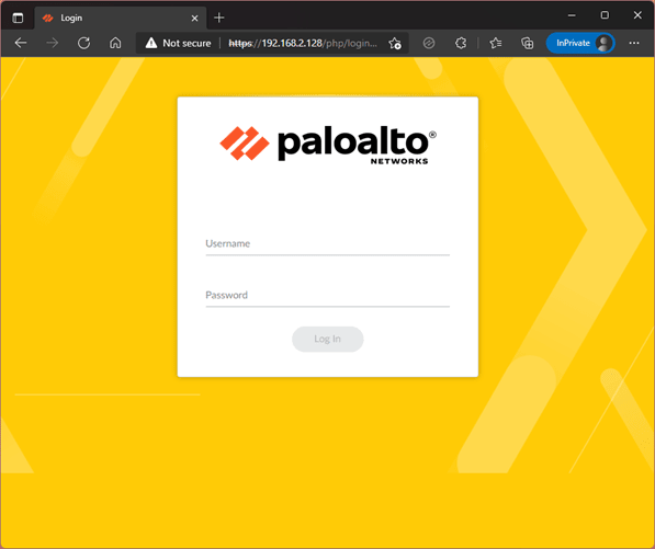
Open the browser and type https://192.168.0.128
You will be presented with the security warning, ignore that and you should now be able to see the palo alto web GUI page, where it is prompting you to enter the username and password.
Enter the username as admin and Password you reset before.

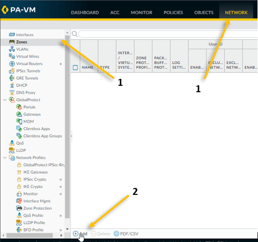
7. Palo alto Firewall Zone creation.
The management configuration is done, and we are now able to access the firewall using the management IP.
Next we need to configure the zone for the inside as well as the outside.
- Click on Network and click on Zone.
- On the down bottom left corner, click on Add to add a new Zone.

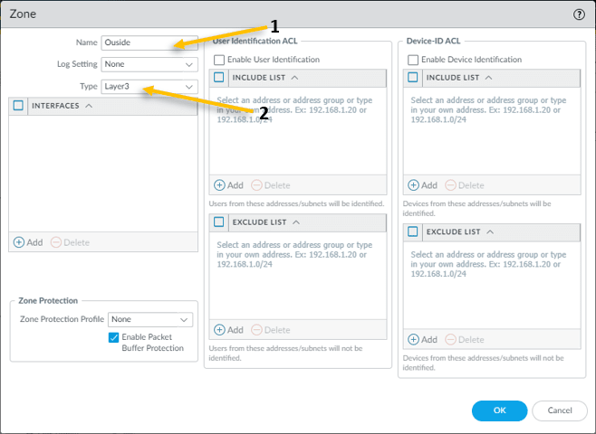
- Provide the name – Outside
- Select the interface type Layer3 and click on Ok.
We don’t have any interfaces to add yet, which we will be doing it next.

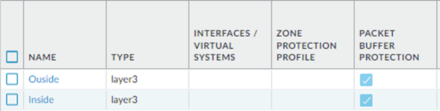
The outside Zone is created, now click Add button again to create the inside Zone with the layer3 type.
You have now created the outside and inside zone.
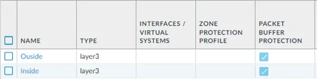
After the commit was successful, let’s go ahead and configure interfaces to be part of these zone.
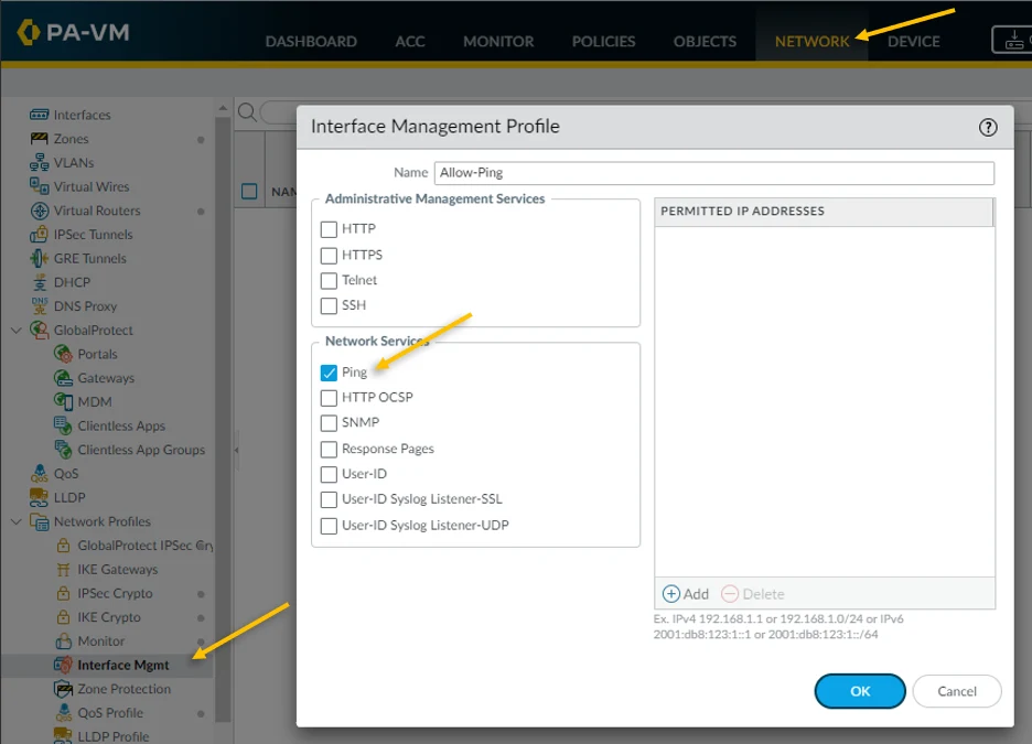
6. Interface Management profile creation.
Let’s allow create the management profile for the interface, that way whatever the service such as Ping, SSH, HTTP etc. available from the beginning.
Click on the Network tab and under Network profiles click on Interface Mgmt.
On the screen, click on Add on the left bottom corner to add the interface management profile.
Name the profile as Allow-ping and tick the Ping option and click on Ok. This will enable the ping on the interface where management profile you applied to.

8. Create the outside interface.
We have configured the second interface as Bridged mode on the VMware workstation, and we are going to configure the same interface on the Palo alto firewall as well.
Go to the Network and click on the interfaces.
The first interface ethernet1/1 is our outside interface connected to the Bridge, after the configuration, the outside interface will start to receive the IP address from the DHCP service on my LAN router.
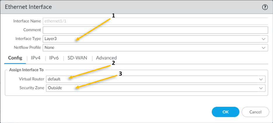
Click on the Ethernet1/1, the interface configuration window will pop up.
- Choose the interface type as Layer3
- In the config tab attach the virtual router as default
- In the security zone choose the outside Zone we created earlier.

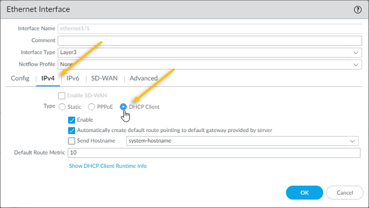
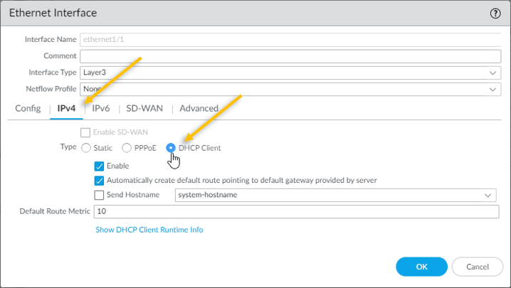
Click on the IPv4 tab.
As we are going to configure the outside interface as DHCP, tick the DHCP Client.
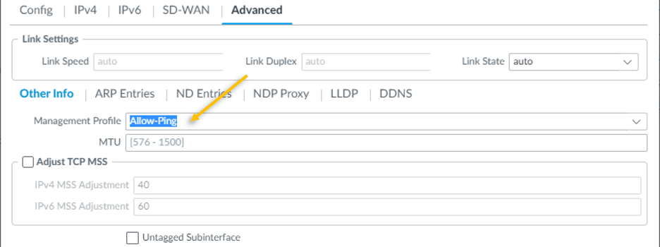
Click on Advanced tab.
Under Other info, you need to attach the management profile that we created earlier, from the management profile drop down, select Allow-Ping and click on OK.

Commit the configuration you just made, by clicking commit on the right top corner.
9. Validate the outside interface.
We just configured the outside interface as a DHCP client, how do you see the IP address configured on the interface?
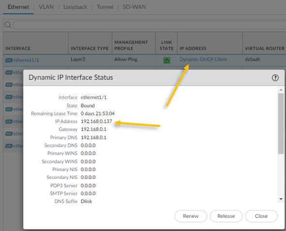
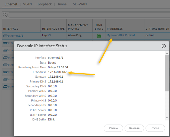
On the interfaces tab, under IP address you should be able to see Dynamic-DHCP client, click on that and that will show the IP address configured on the interface.
As you can see the we got the ip address 192.168.0.137 from my internet router.
10. Verify the ICMP traffic.
You should now be able to reach the internet using the outside interface.
Login to the CLI and try to ping google public DNS IP 8.8.8.8 sourcing from the outside interface and you should be able to reach the internet.
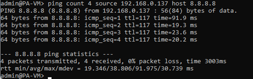

In case if you are wondering, how the private IP address on my firewall able to reach the public IP address on the internet?
It is because, my internet router is acting as NAT device which translate the outside private IP (192.168.0.137) to my internet public IP when it goes out to the internet.
11. Configure the inside interface.
Like how we have configured the outside interface, lets go ahead and configure the inside interface.
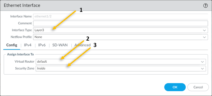
You can go back to the network and click on interfaces, in the interfaces click on ethernet1/2 which is our internal interface.
- Configure the interface Type as Layer3.
- In the config tab, choose the virtual router as default.
- And the security zone as inside.

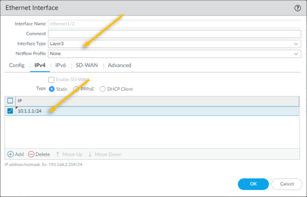
You may click on the IPv4 tab now.
All our Lan users will be connected to the inside interfaces, and remember we disabled the DHCP from the VMware workstation ? so, we are going to configure the IP address manulaly here.
The IP address that we are going to configure is 10.1.1.1/24.
Click on Static and add the same Ip address.

Click on Advanced tab
To enable the ICMP on the inside interface, lets attach a management profile that we created.
Click on Advanced tab Add the management profile allow-ping here.

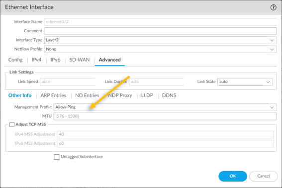
Click on Ok and commit the configuration.
So far, we configured the management interface, and created the outside and inside zones, then added outside interface that is connected to the internet and another inside interface that is connected to the LAN.
12. Configure the LAN users to access the internet.
The next objective is to allow inside users to outside so that they can access the internet. Follow the steps below to accomplish that.
- Configure the policy to allow inside users to outside.
- Configure NAT policy
- Configure the DHCP server.
1.Configure the policy to allow inside users to outside.
We are going to allow the inside users to talk to the outside world in Palo alto firewall, to do that we need to configure security policies on the firewall.
Click on Policies tab and click on Security
Click on the Add button to add the security policy.
- Provide a Name – Allow_Inside_to_Outside
- Click on Source – Choose the source Zone as Inside.
- Source Address – 10.1.1.0/24
- Click on Destination tab – Choose the destination zone as outside.
- Click on the Action tab and choose the action to allow and click on OK.
That’s it, you just configured the policy to allow the end users to reach the outside.
2. Configure the NAT policy.
We know that our outside interface can go out to the internet using LAN routers NAT function, however when the inside users 10.1.1.0/24 wanted to go off the internet the firewall will have to do the NAT for the inside address.
In the same Policies tab, click on NAT on the left side.
Click on the Add button.
- On General tab, in Name field Provide a Name – NAT_Inside_to_out10
- Click on the Original Packet – Select the source zone as Inside.
- Destination Zone as Outside.
- Destination interface as ethernet1/1
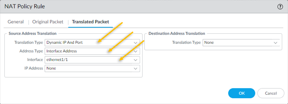
- Click on Translated Packet.
- We need the source IP 10.1.1.0/24 to get translated to the outside interface IP which is 192.168.0.137. hence under Source Address Translation, choose Dynamic IP and Port.
- Address Type – Interface Address.
- Interface – Ethernet 1/1 (Outside interface)

3. Configure the DHCP server.
For the end users to talk to the outside world the end user machine should have IP configured, you can configure the IP as static or dynamic. We are going to configure the dynamic IP configuration on the Paloalto firewall using the DHCP.
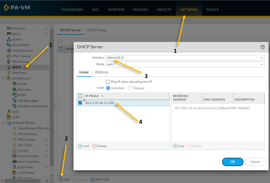
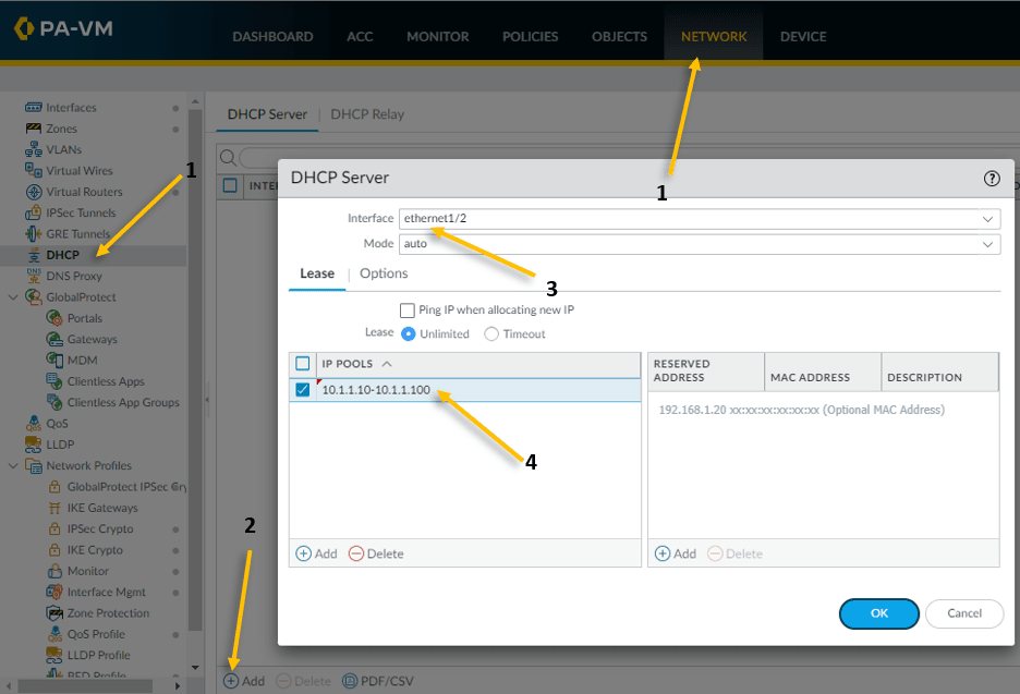
- Click on the network and click on DHCP on the left.
- Click on Add to configure the DHCP service.
- Our inside LAN interface is ethernet1/2 hence choose that.
- We are going to configure the IP address range from 10.1.1.10-10.1.1.100 so configure the pool accordingly.
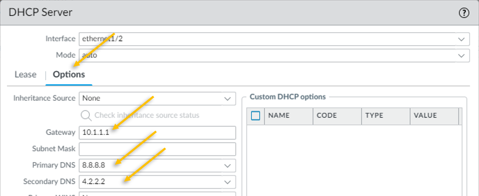
Click on the Options tab.
- Configure the gateway as 10.1.1.1
- Configure the Primary and secondary DNS as 8.8.8.8 and 4.2.2.2 respectively.

That’s it, you have successfully configured the DHCP, go ahead and commit the changes on the firewall.
13. Test the connectivity.
Let’s assume for a second our current setup with the real Network. We have configured everything with respect to the Network or the infrastructure, now you need to ask the users to start connecting their host to the Network to test the connectivity. So, in the VMware lab environment how do we do that.
We can rely on the virtualization again.
I have already configured the Windows 11 in VMware workstation and IP configuration is automatic, since the inside interface is connected to the VMnet1, I also moved the windows 11 interface VMnet1 (Host only Adapter).
Lets power on the VM.
As soon as WIndows 11 came up, it got the IP address 10.1.1.11 – The Second IP on the DHCP pool that we configured.
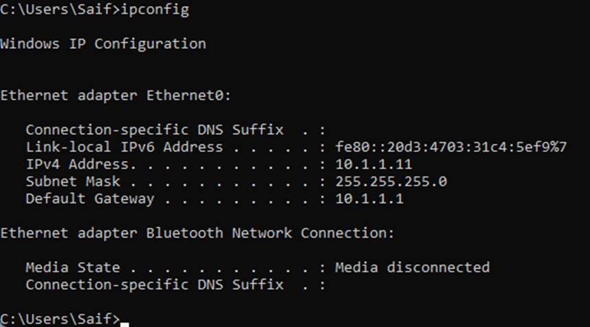
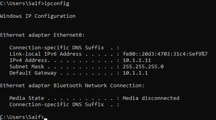
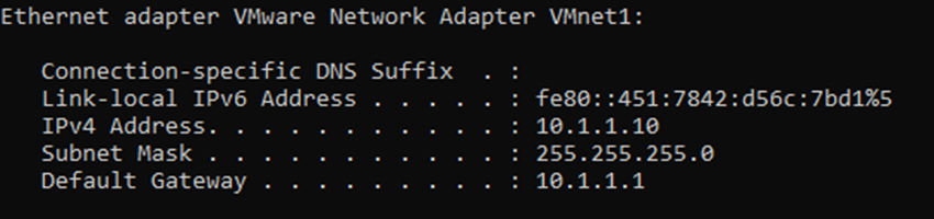
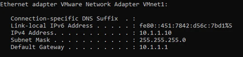
But what about the first IP, it turns out 10.1.1.10 was automatically assigned to my host VMnet1, as you can see below.
Lets try to ping google also do a traceroute.
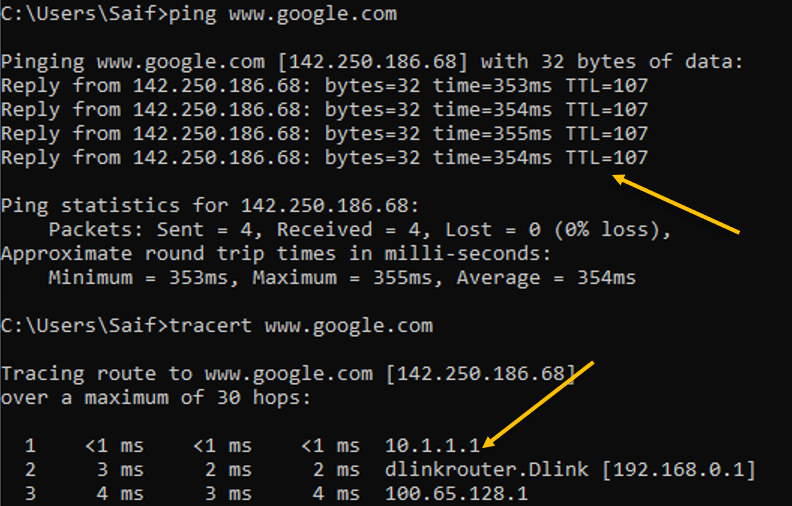

As you can see above, the ping was successfull to the internet and the traceroute was taking the first hop which is the inside IP address 10.1.1.1
Next hop is my internet router.
3rd hop is off to the internet.
Lets also try to browse the internet.
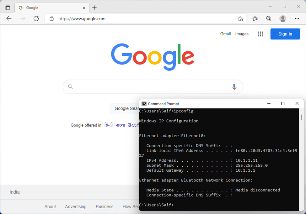
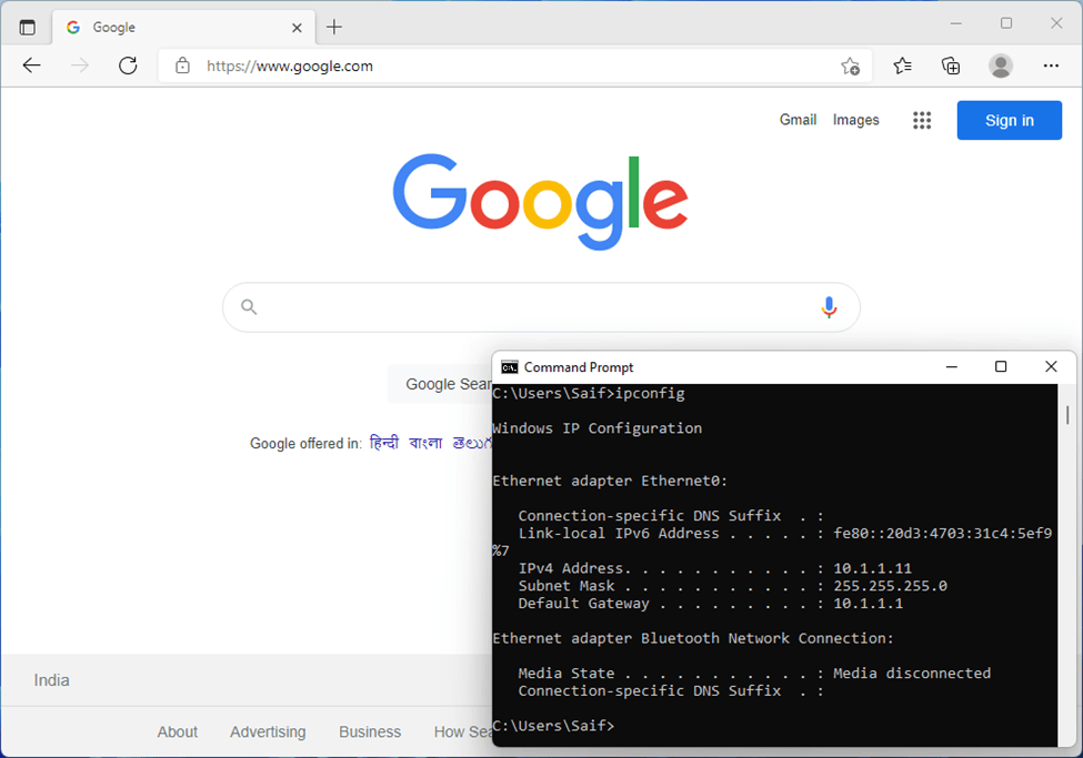
And as you can see, I can browse the internet just fine as well.
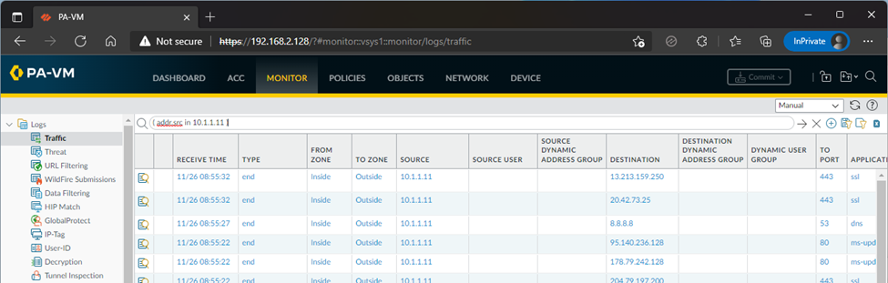
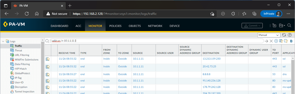
You can observe the traffic on the Paloalto firewall by going to Monitor and the traffic tab.
One thing I am happy about after version Paloalto10 is that, without license we can see the logs in the monitor tab now, that was not the case for the previous versions.
We have successfully configured a simple Palo alto lab using VMware workstation. We can do many more with unlicensed Paloalto firewall VM and it should work fine. But there will be certain roadblocks with respect to configuring the advanced features of the Palo alto firewall. However, for those who wanted to start off, the unlicensed version is the great place to start.