
We have looked at how you can set up an IPsec VPN between two FortiGate firewalls in our last blog article, and it works great. But sometimes you will have multiple subnets that you would want to route through the FortiGate firewall, so how do you route multiple subnets across the IPsec tunnel using the FortiGate firewall ?
In this blog, we are going to take a look at how you can configure IPsec vpn between two FortiGate firewalls with multiple subnets. At the end of the article you will have a working VPN with remote sites able to communicate using multiple subnets.
Below is the topology that we are going to work on. We have two sites, one on the left is the headquarters and the one on the right is the branch site. The headquarters has the subnet of 10.1.1.0/24 and 172.16.0.0/24 and the branch site has 10.2.2.0/24 and 10.200.200.0/24.

Both sites at the moment can go out to the internet, that’s it, and the LAN side cannot talk to each other, because there is no site to site connectivity.
We are going to build an IPsec tunnel which will enable the communication between these two sites over an encrypted IPsec tunnel using multiple LAN subnets, so let’s get started.
Configure the IPsec at the Headquarters
We will start the configuration at the Headquarters and then we will move on to the branch site.
Configure the Phase1 of the IPsec configuration on Headquarters.
We are going to set up phase1 of the IPsec tunnel.
Login to the FortiGate firewall and then goto VPN-> IPsec tunnels -> Click on Create new-> IPsec tunnel.
Note: if you have taken to IPsec configuration wizard, you may choose custom.
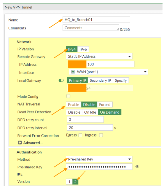
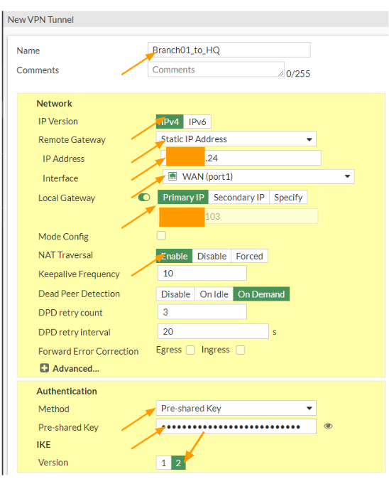
Name: IPsec_branch01 and click on Next.
IP Version: Choose IPv4
IP address: Enter the public IP address of your remote site.
Interface: choose the outside interface from the dropdown.
Toggle the Local Gateway option, and choose primary IP to select the outside public IP address.
NAT Traversal: As I am not connected to the firewall behind a NAT device, I could disable the NAT traversal option.
Authentication: for authentication we are choosing the pre-shared key from the drop down.
Pre-shared key: enter a secure pre-shared key.
IKE : choose the version 2.

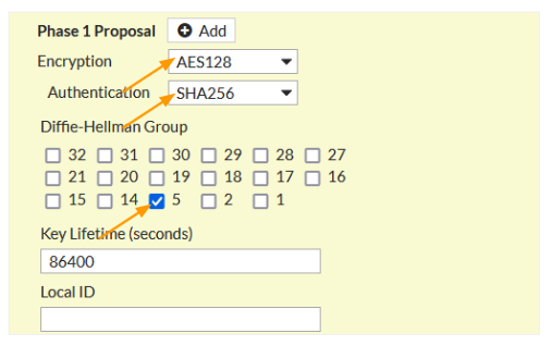
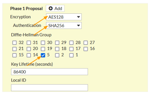
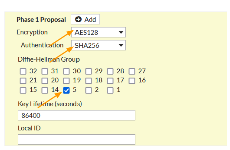
Phase1 Proposal.
Here choose the encryption and authentication.
Encryption: AES128
Authentication: Sha256
DH Group: 5
Phase 2 configuration with multiple subnets.
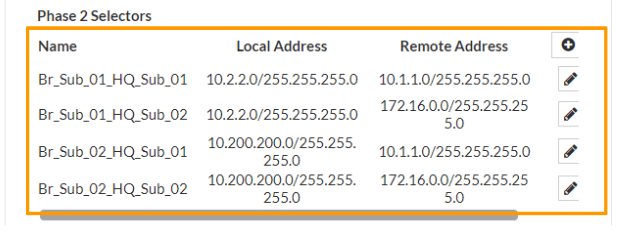
Scroll down to Phase2 selectors.
Add the multiple subnets one by one.
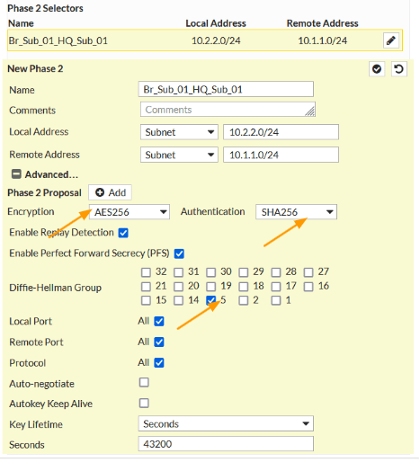
New Phase2
Name: Enter the name of the first subnet pair, it should have a local subnet and the remote and it is important that both sides match when you set the phase2 on the branch side.
Local Address: Choose subnet and Enter the HQ local address which 10.1.1.0/24
Remote Address: choose subnet and enter the branch01 subnet 10.2.2.0/24 as well.
Phase2 Proposal.
Encryption: AES256
Authentication: SHA256
DH group: 5
Click on the check mark to add the first subnet, and continue to add other subnets as well. It is important to note that, whatever the Phase2 parameters that you mentioned here should match on the remote side as well.
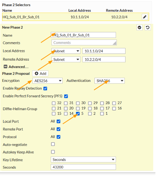

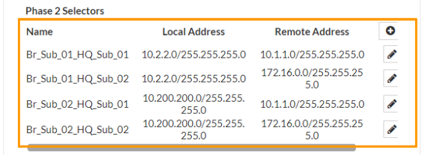
As You can see, I have added a total of 4 phase2 interesting traffic.

Configure the IPsec Static Route.
We have setup the IPsec tunnel, for any traffic that is destined for the remote subnet 10.200.200.0/24 and 10.2.2.0/24 will by default take the default route to go out and it will fail, so we need to point these routes to take the IPsec tunnel interface.
So let’s configure the static route so that the traffic will send to the IPsec tunnel.
Add the first subnet route.
Goto-> Network-> Static routes.
Click on Create New to create a new static route.
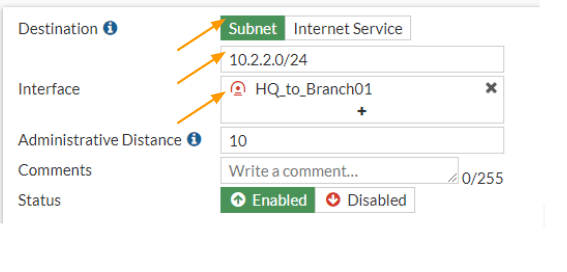
Destination: subnet.
Enter the remote subnet address which is 10.2.2.0/24
Interface: IPsec tunnel interface that we just created.
Click on Ok.

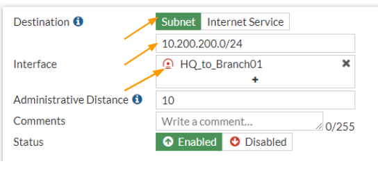
Add the second route.
In the same static routes configuration screen, click on create new again to add routes fro 10.200.200.0/24 network.
Destination: subnet
Enter the subnet 10.200.200.0/24 network.
Interface: choose the IPsec interface that we created.
And click on Ok.

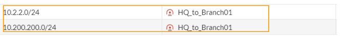
You can now see two routes are defined in the FortiGate firewall.

Configure the security to policies for IPsec multiple subnets
We guided all the traffic destined for 10.2.2.0/24 and 10.200.200.0/24 to take the IPsec tunnels, however the FortiGate firewall will block this traffic, so we need to create a security policy to allow the traffic that are going in and out of the firewall.
To make our configuration task easier, we are going to add both the destination and source subnet as address groups, which can be called easily to the security policies.
Configure the branch01 address object.
We are going to add both the 10.2.2.0/24 and 10.200.200.0/24 addresses to branch01 address object group, so it will be easy to call the branch01 network subnet during the policy creation.
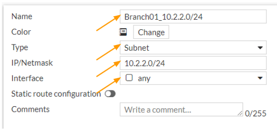
Create the first branch01 address object.
Goto Policy & Object -> Addresses-> Create new-> Address
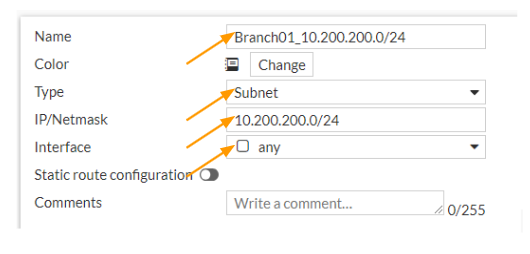
Name: Enter the name of the subnet, it is best to add the subnet information in the name, so it is easy to identify during policy creation.
Type: Subnet
IP/Netmask: 10.2.2.0/24
Interface: any

Create the second branch01 address object.
Click on create new-> address
Name: enter the address object name
Type: Subnet
IP/Netmask: 10.200.200.0/24
Interface: any

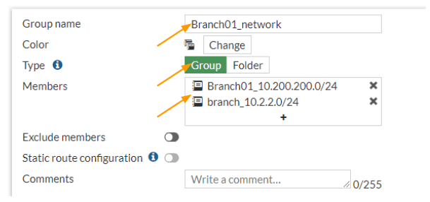
Create an Address group.
With the addresses that we added, we are now going to create an address group that will have both the addresses that we defined.
In the same addresses screen, click on create new drop down and in the drop down choose the address group this time.
Group name: Branch01 network.
Type: Group
Members: add both the subnets that we defined.

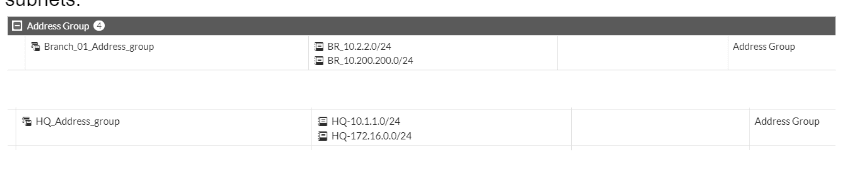
Create the Headquarters address object.
Same way we configured the address object for the destination network, we are also going to configure the address object and its group for the headquarters network as well.
The subnet that we are going to use for the headquarters networks are 10.1.1.0/24 and 172.16.0.0/24.
As you can see, I have added both the networks in the addresses.

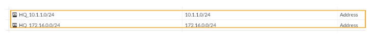
And created the following address group.
This group now can be called into the network security policies.


Configure the Security Policy for the IPsec traffic.
We got the Address group ready, let’s now go ahead and create the security policies for both incoming and outgoing traffic.
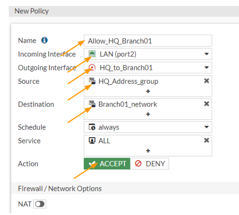
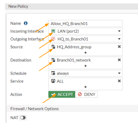
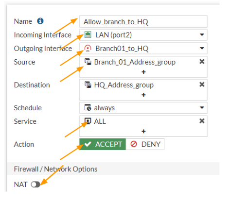
Configure the outbound policy.
When we say outbound traffic, we are referring to the traffic initiated from the HQ LAN side to the remote branch network.
Goto Policy & Objects -> Firewall Policy-> Create New
Name: Enter a meaningful name.
Incoming interface: Choose LAN.
Outgoing interface: IPsec interface of branch01
Source: Choose the Address group that we defined.
Destination: Choose the Branch01 address group that we defined.
Action: Accept.
Uncheck the NAt option and enable log Allowed traffic and then click on Ok.
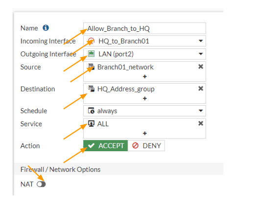
Configure the Inbound policy.
We allowed the traffic that is going out from the HQ LAN side, now you need to also allow the traffic that is coming from the branch side as well.
In the policy definition screen, click on create new.
Name: Enter a name.
Incoming interface: we know that the traffic will be coming from the Branch01 IPsec interface, so choose that.
Outgoing interface: Choose the LAN, or inside interface where you have the local traffic.
Source: Choose the branch network address group.
Destination: Choose the HQ address group.
Service: All.
Action: Accept.
Uncheck NAT.
Check the box for log Allowed traffic and then click on Ok.

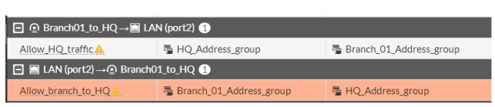
The policy configuration at the headquarters site is now complete and we allowed both outgoing and incoming traffic.
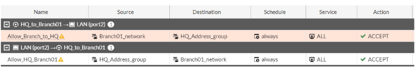
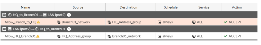
Why is it an exclamation mark next to the policy?
If you are wondering why there is an exclamation mark next to the policy that we defined, its because the IPsec tunnel interface is down at the moment, only when the IPsec tunnel interface comes back up, you will see the exclamation mark goes away.
That’s all the configuration we got to do at the headquarters, let’s move on to branch01 and configure the same.
Configure IPsec at the branch01 site.
We are now going to configure the IPsec at the branch site with exact same steps that we followed at the Headquarters. we will start with phase1 of the configuration.
Configure Phase1 of the IPsec configuration at the branch site.
Login to the branch01 FortiGate firewall, and the goto VPN-> IPsec tunnels -> Create New.
Name: Enter the name of the tunnel.
IP Version: Ipv4
Remote gateway: Static IP address
IP address: Enter the public IP address of the HQ site.
Interface: choose the Outside interface where you configured the public IP.
Local gateway: check this option, and choose Primary IP.
NAT Traversal: Disable.
Authentication:
Method: pre-shared key.
Pre-shared key: Paste the pre-shared key that you copied front he hq site.
IKE: choose the version 2.

In Phase1 proposal.
Choose Encryption: AES128
Authentication: Sha256
DH Group: 5
Phase1 proposal.

Phase2 configuration at the branch with multiple phase2 selectors.
Like we added the hq phase2 subnets, we are going to add the interesting traffic at the branch site as well.
As you can see, I am adding the subnet which is right opposite of the HQ site, meaning, while I selected Local address 10.1.1.0/24 in HQ, here that would become the remote address. Similarly, the local Address 10.2.2.0/24 is the remote address at the HQ site.
Phase 2 Proposal.
Click on Add, if you don’t have already, and choose as below.
Encryption: AES256
Authentication: SHA256
Diffie-Hellman Group: choose 5
Click on the check icon to add the first subnet, similarly add the other subnets as well according to the hq site.

As you can see, like we added 4 phase2 selectors in HQ, we have done the same thing on the branch site as well.
Configure the static route for the tunnel.
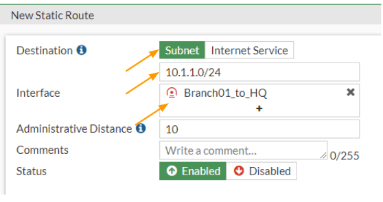
We have to now tell the branch01 firewall to send any traffic destined to 10.1.1.0/24 and 172.16.0.0/24 to take the IPsec tunnel as the path.
Goto Network -> Static routes -> Create New.
Destination: Subnet
10.1.1.0/24
Interface: IPsec towards the hq site.
Click on Ok.

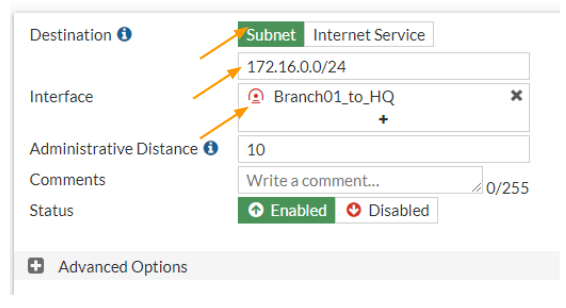
Create new again.
Destination: Subnet
172.16.0.0/24
Interface: Choose the IPsec towards the HQ and click on OK.
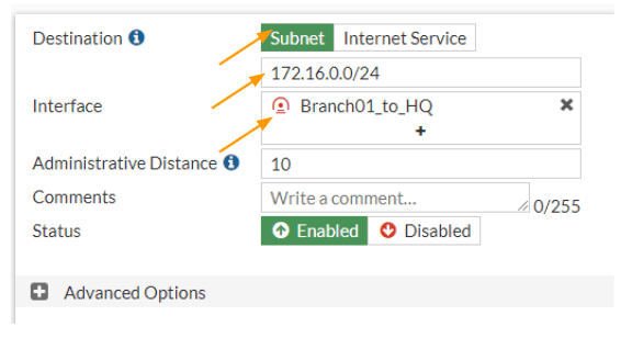
We have two routes added towards the hq site.


Configure the security policy for the tunnel.
Add the address group in fortigate.
Like we did before, let’s configure the address group for both source and destination subnets. By going into Policy&Objects-> Addresses
As you can see, I have created two address groups for both HQ subnets and Branch01 subnets.

Let’s now configure the Security policy for both inbound and outbound traffic for the IPsec tunnel that we created.
Configure the IPsec security policy.
We will start with an inbound policy and then we will create an outbound security policy.
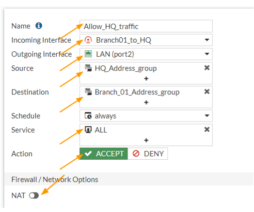
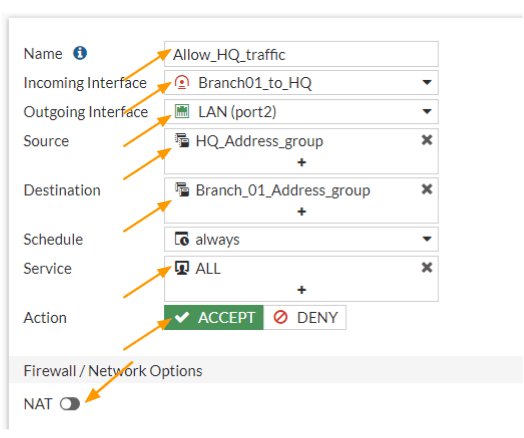
Configure the inbound policy.
Goto Policy& Objects -> Firewall Policy -> Create new.
Name: Enter the name for the policy.
Incoming interface: we are allowing the traffic coming from the HQ, so it will be the IPsec tunnel that we just build.
Outgoing interface: choose the LAN or inside interface.
Source: Choose the HQ address group that we defined.
Destination: Choose the Branch address group that we created.
Service: All
Action: Accept
Uncheck the NAT option.
Check the option that says, Log allowed traffic and then click on Ok.
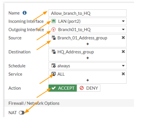
Configure the Outbound Security Policy.
We are now going to create another policy for outgoing traffic from the branch, this will be the opposite of the previous policy.
Click on Create New again, on the security policy creation screen.
Name: Enter the name for the policy.
Incoming interface: LAN
Outgoing interface: Choose the IPsec tunnel interface.
Source: Choose the Branch subnet address group.
Destination: Choose the HQ address group.
Service: All.
Action: Accept.
Uncheck the NAT option, and check the option that says Log Allowed Traffic and then click on OK.

Test the IPsec connectivity.
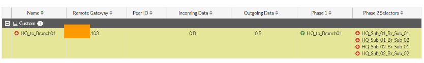
At this point, when somebody initiates traffic from each side, you will see the IPsec tunnel come up, if there is no traffic and you want to test and see if the tunnel comes up or not. You could go to Dashboard-> Status-> IPsec tunnel status (If you don’t see the status in the dashboard, you will have to add the IPsec status widget), or the older version the same status will be at monitor-> IPsec tunnels.
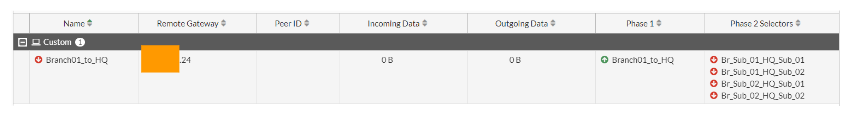
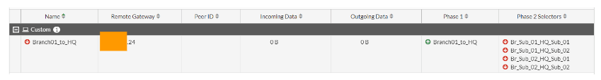
As you can see, only the phase1 of the tunnel is now up (indicating the green up arrow), and all the multiple subnets in phase2 are currently down on both the HQ and the branch locations.
HQ IPsec phase1 and phase2 status.
Branch IPsec phase1 and Phase2 status.
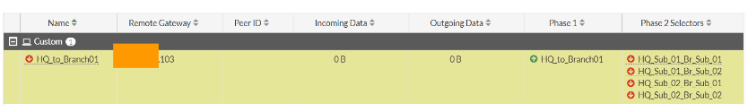
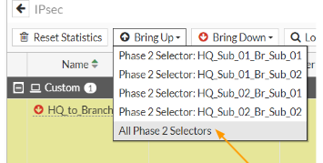
To manually bring up the tunnel, click on the bring up drop down and click on All Phase2 selectors.

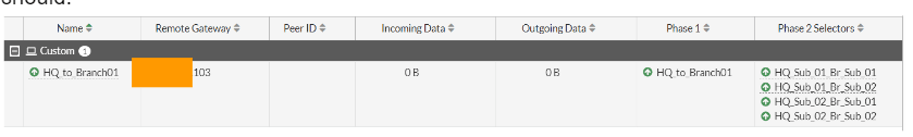
As you can see, both the phase1 and phase2 of the tunnels are up with multiple subnets.
You can now test the connectivity from both the sides to see if everything is working as it should.

Validate the connectivity from both the sites.
Test the connectivity from the HQ site to the branch.
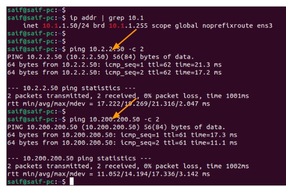
Lets login to the HQ PC 10.1.1.50 and try to ping branch01 pc1 10.2.2.50 and pc2 10.200.200.50
As you can see, I am able to reach both the remote subnets.

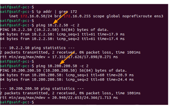
I have tried the same thing from the second subnet in the HQ site, and I can reach both the subnet as well.

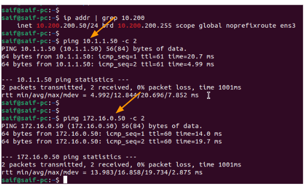
Test the connectivity from the branch01 to the HQ site.
I have now logged into the PC in 10.2.2.0/24 subnet, and tried to ping hq site, as you can see that was successful as well.
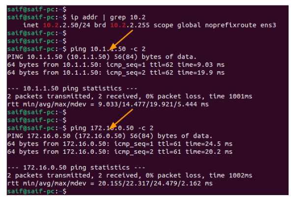
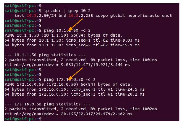
Same case with the second PC to the HQ site as well.

We have now successfully set up an IPsec tunnel with multiple subnets on the FortiGate firewall. If you see phas2 doesn’t come up for some reason, it is most likely because of the following.
- The Subnet mismatch at each end, it is important to match both sides.
- Or Phase2 IPsec parameters parameters are incorrect.
- Finally check the routes and policy configurations.
Jaren
Monday 16th of March 2026
What could be the issue if after everthing is setup, I can ping everything at HQ from a PC at Branch01, but at HQ I can only ping the gateways of each subnet but not any PC's on those subnets?