Ever since Ubuntu changed its network configuration utility to netplan from the traditional configuration, many of them got so upset. Some of them are very annoyed that they even entirely removed the netplan and installed ifupdown back into the system.
So is Ubuntu Netplan going to stay ?, if yes shouldn’t we learn how to configure them on our Ubuntu machine?
The answer to both the questions is Yes; after researching the netplan, it looks like it’s going to stay.
Now the option that we have is to either install the ifupdown, which you never know how long it would be available or accept the change and learn the netplan configuration.
If you are ready to accept the change then let’s get started.
The Ubuntu netplan uses a script called Yaml (Yet Another Markup Language) to generate its network configurations.
And the network interfaces and configurations can be defined as separate blocks in it.
In this blog, we would look at netplan examples with which we could create a network in Ubuntu 18.04 or above.
Read also,
Netplan Route via Interface – How to Configure It?
How to Configure Bridge Interfaces Using Netplan in Ubuntu?
How to Configure LACP Bonding Using Netplan in Ubuntu?
Note: The configuration below is tested and verified working in my lab environment running Ubuntu 19.04, so in case if you are facing any issue with configuration please do let me know via email.
Most of the labs I am using with Ubuntu 19.04, but these steps are still relevant for version 18.04 and above.
Before you do anything make sure you take the backup of the existing configuration
Follow the below steps to take the backup in the same /etc/netplan directory
sudo cp /etc/netplan/01-network-manager-all.yaml /etc/netplan/01-network-manager-all.yaml.bak
or
sudo cp /etc/netplan/50-cloud-init.yaml /etc/netplan/50-cloud-init.yaml.bak
- How to configure DHCP using netplan
- How do I set a static IP on netplan?
- How to Set DNS Server in netplan?.
- Ubuntu configure multiple static IP.
- How to add secondary ip address ubuntu?
- How to create Bond interface with VLAN tagged?
- How to tag multiple VLAN’s in a Bond using netplan?
- How do I tag VLAN on Ubuntu using Netplan?.
If you are using WiFi and wanted to configure the netplan on your Ubuntu machine, then you may click here, I have covered the complete article there for WiFi.
How to configure dhcp using netplan?
By default you don’t have to create or modify anything in netplan if you are planning to use DHCP, the Ubuntu machine will have an IP address configured automatically via DHCP out of the box. And this is how netplan config looks like from the Ubuntu server.
gld@ubuntu:~$ cat /etc/netplan/50-cloud-init.yaml
# This file is generated from information provided by
# the datasource.  Changes to it will not persist across an instance.
# To disable cloud-init's network configuration capabilities, write a file
# /etc/cloud/cloud.cfg.d/99-disable-network-config.cfg with the following:
# network: {config: disabled}
network:
    ethernets:
        ens33:
            dhcp4: true
    version: 2
gld@ubuntu:~$
If the dhcp4 is marked as false in your Ubuntu server, then you may change to true to start getting the IP address dynamically.
What if you are Ubuntu desktop user, then it would look like below.
gld@ubuntu:~$ cat /etc/netplan/01-network-manager-all.yaml
# Let NetworkManager manage all devices on this system
network:
  version: 2
  renderer: NetworkManager
gld@ubuntu:~$
What are the differences you could spot between these two ?
There is a renderer mentioned in the Ubuntu Desktop but not on the server.
Although DHCP enabled on both of them, Ubuntu server has the value dhcp4: true, but not on the Desktop.
Also the yaml file name is different.
As you can see the yaml configuration changed from cloud-init to network manager, sometimes the configuration would look like 01-netcfg.yaml
It may be even different in your machine as well, so make sure you are editing the correct file.
How do I set a static IP on netplan?
The issue starts when you want to configure netplan static IP on an interface. However, configuring static IP on Ubuntu using netplan is not so difficult. Let’s look at how we can configure a single static IP using netplan.
Here is the basic topology that we are going to use.
The above diagram is a common example if you connect a server to a network, or even at home, you are using a Ubuntu box that requires you to have a static configuration.
1. Get the physical interface name.
You have to type ip addr command to get the physical interface names to edit the yaml file. I have typed the same and my interface name is eno2.
saif@saif-pc:~/Desktop$ ip addr
1: lo: <LOOPBACK,UP,LOWER_UP> mtu 65536 qdisc noqueue state UNKNOWN group default qlen 1000
    link/loopback 00:00:00:00:00:00 brd 00:00:00:00:00:00
    inet 127.0.0.1/8 scope host lo
       valid_lft forever preferred_lft forever
    inet6 ::1/128 scope host
       valid_lft forever preferred_lft forever
2: eno2: <BROADCAST,MULTICAST,UP,LOWER_UP> mtu 1500 qdisc fq_codel state UP group default qlen 1000
    link/ether 04:d4:c4:e3:88:2d brd ff:ff:ff:ff:ff:ff
    inet 192.168.0.71/24 brd 192.168.0.255 scope global noprefixroute eno2
       valid_lft forever preferred_lft forever
2. Edit the Netplan configuration.
Edit the netplan configuration file by typing the command below
sudo nano /etc/netplan/01-network-manager-all.yaml
By default you would have the following values.
network:
        version: 2
        renderer: NetworkManager
- As we can see in the diagram we should assign an IP address 192.168.0.100/24 to the host. Hence add the addresses and gateways according to the diagram.
network-manager-all.yaml
network:
        version: 2
        renderer: NetworkManager
        ethernets:
             eno2:
              dhcp4: no
              addresses: [192.168.0.100/24]
              gateway4: 192.168.0.1
              nameservers:
                search: [local]
                addresses: [4.2.2.2, 8.8.8.8]
3. Apply the config.
Apply the configuration changes you just made by entering sudo netplan apply
4. Validate the change.
Type the command ip addr to confirm the change. As you can see you got the new IP address as we defined.
2: eno2: <BROADCAST,MULTICAST,UP,LOWER_UP> mtu 1500 qdisc fq_codel state UP group default qlen 1000
    link/ether 04:d4:c4:e3:88:2d brd ff:ff:ff:ff:ff:ff
    inet 192.168.0.100/24 brd 192.168.0.255 scope global noprefixroute eno2
       valid_lft forever preferred_lft forever
    inet6 fd01::88a6:fd02:464:8530/64 scope global temporary dynamic
       valid_lft 163sec preferred_lft 163sec
    inet6 fd01::f972:645c:8325:1c0f/64 scope global dynamic mngtmpaddr noprefixroute
       valid_lft 163sec preferred_lft 163sec
    inet6 fe80::c425:4e18:1808:52bb/64 scope link noprefixroute
       valid_lft forever preferred_lft forever
5. Verify the connectivity.
Let’s ping the gateway of the host and see if we are able to ping the IP address 192.168.0.1
saif@saif-pc:~$ ping -c 4 192.168.0.1
PING 192.168.0.1 (192.168.0.1) 56(84) bytes of data.
64 bytes from 192.168.0.1: icmp_seq=1 ttl=255 time=9.35 ms
64 bytes from 192.168.0.1: icmp_seq=2 ttl=255 time=7.18 ms
64 bytes from 192.168.0.1: icmp_seq=3 ttl=255 time=3.50 ms
64 bytes from 192.168.0.1: icmp_seq=4 ttl=255 time=3.62 ms
--- 192.168.0.1 ping statistics ---
4 packets transmitted, 4 received, 0% packet loss, time 3005ms
rtt min/avg/max/mdev = 3.506/5.916/9.352/2.473 ms
Also, try to ping the google address to make sure that the internet is working fine as well.

well, we are able to ping the gateway IP as well as the google address successfully and everything is up and running.
How to Set DNS Server in netplan?
In the previous step, did you notice last line which says name servers ?
That is nothing but the DNS entries.
If you just configure the static IP address alone without DNS, you will not be able to access the internet. So you need to make sure that you also defined the DNS servers.
If otherwise you are trying to access the internet with just IP addresses 🙂
Lets see what happens if you remove the nameservers.
1. DNS lookup using NSLOOKUP.
I just removed the name server configuration from the netplan configuration, If you try to access google.com now, you would get no response as we have not defined the DNS configuration on Ubuntu.
Let’s quickly check the DNS resolution by doing nslookup.
saif@saif-pc:/etc/netplan$ nslookup www.google.com
 Server:         127.0.0.53
 Address:        127.0.0.53#53
 ** server can't find www.google.com: SERVFAIL
 saif@saif-pc:/etc/netplan$
see, the nslookup failed.
To configure the DNS in Ubuntu using netplan, you may go ahead and add the value nameserver, that defines the DNS server IP and search for the domain name.
2. DNS configuration.
Edit the netplan configuration file again and add the values like below.
- If you don’t have any internal DNS configured you can configure the nameserver like below pointing to public DNS servers.
network-manager-all.yaml
network:
        version: 2
        renderer: NetworkManager
        ethernets:
             eno2:
              dhcp4: no
              addresses: [192.168.0.100/24]
              gateway4: 192.168.0.1
              nameservers:
                search: [local]
                addresses: [4.2.2.2, 8.8.8.8]
- If you have internal DNS configured then you may change it according to your local network, for example like below.
As you can see I have netplan domain name as getlabsdone.local. , hence I have added them on the search filed.
 nameservers:
                search: [getlabsdone.local]
                addresses: [10.1.1.10, 10.1.1.20]
3. Apply the configuration.
I have pointed to the public DNS servers and, lets go ahead and apply the netplan configuration.
sudo netplan apply
4. Verify the DNS configuration.
You can check the DNS name resolution by typing nslookup command again.
As you can see I am getting the DNS query response now, which means DNS configuration is working on the Ubuntu machine.
saif@saif-pc:~$ nslookup www.google.com
 Server:         127.0.0.53
 Address:        127.0.0.53#53
 Non-authoritative answer:
 Name:   www.google.com
 Address: 216.239.32.117
 Name:   www.google.com
 Address: 216.239.36.117
 Name:   www.google.com
 Address: 216.239.38.117
 Name:   www.google.com
 Address: 216.239.34.117
 Name:   www.google.com
 Address: 2404:6800:4007:80e::2004
 saif@saif-pc:~$
Ubuntu configure multiple static IP
Configuring the static IP address on multiple interfaces on Ubuntu are identical to how we configured static IP on a single interface, let’s take a look configuring static IP’s on multiple interfaces with Netplan.
I have a Ubuntu machine connected to a network with SIX interfaces ( ens3f0, ens3f1, ens5f0, ens5f1, ens6f0, ens6f1 ), and please note that the name could be different on your machine so making a note of the physical interface is very important. And you can get the physical interface name by typing ip addr in the terminal.
Those SIX interfaces are connected from the switch to the Ubuntu machine as shown below, each having different IP from the same subnet.

1. Edit the Netplan Yaml file.
To edit the yaml file enter the command below.
sudo nano /etc/netplan/50-cloud-init.yaml
2. Configure the IP addresses.
Follow the steps below to configure a physical interface statically.
- Mention the block ‘ethernets‘
- Just below that define the physical interface.
- DHCP is set to false.
- Mention the Address field for each interfaces.
- Finally the Gateway4 for all the interfaces.
This is how the configuration look like for a single interface.
ethernets:
        ens3f0:
          dhcp4: no
          addresses: [10.25.101.206/24]
          gateway4: 10.25.101.1
3. Configure all the interfaces
As I mentioned earlier, in my machine I have multiple interfaces and I would have to configure the IP address to all of them, so edit the yaml file in the following sequence.
# Let NetworkManager manage all devices on this system
network:
    version: 2
    renderer: NetworkManager
    ethernets:
        ens3f0:
          dhcp4: no
          addresses: [10.25.101.206/24]
          gateway4: 10.25.101.1
        ens3f1:
          dhcp4: no
          addresses: [10.25.101.207/24]
          gateway4: 10.25.101.1
        ens5f0:
          dhcp4: no
          addresses: [10.25.101.208/24]
          gateway4: 10.25.101.1
        ens5f1:
          dhcp4: no
          addresses: [10.25.101.209/24]
          gateway4: 10.25.101.1
        ens6f0:
          dhcp4: no
          addresses: [10.25.101.210/24]
          gateway4: 10.25.101.1
        ens6f1:
          dhcp4: no
          addresses: [10.25.101.211/24]
          gateway4: 10.25.101.1
4. Apply the configuration.
For this chances to affect, you would have to apply the netplan configuration, to do that enter the below command.
sudo netplan apply
5. Verification.
- To verify the configuration, you can type the command
ip addrand it should show you the interfaces with its IP addresses. As you can see the IP address has been changed now for all the interfaces.
2: ens6f0: <BROADCAST,MULTICAST,UP,LOWER_UP> mtu 1500 qdisc mq state UP group default qlen 1000
    link/ether d0:67:26:bb:17:42 brd ff:ff:ff:ff:ff:ff
    inet 10.25.101.210/24 brd 10.25.101.255 scope global noprefixroute ens6f0
       valid_lft forever preferred_lft forever
    inet6 fe80::d267:26ff:febb:1742/64 scope link
       valid_lft forever preferred_lft forever
3: ens6f1: <BROADCAST,MULTICAST,UP,LOWER_UP> mtu 1500 qdisc mq state UP group default qlen 1000
    link/ether d0:67:26:bb:17:43 brd ff:ff:ff:ff:ff:ff
    inet 10.25.101.211/24 brd 10.25.101.255 scope global noprefixroute ens6f1
       valid_lft forever preferred_lft forever
    inet6 fe80::d267:26ff:febb:1743/64 scope link
       valid_lft forever preferred_lft forever
4: ens5f0: <BROADCAST,MULTICAST,UP,LOWER_UP> mtu 1500 qdisc mq state UP group default qlen 1000
    link/ether d0:67:26:bb:10:04 brd ff:ff:ff:ff:ff:ff
    inet 10.25.101.208/24 brd 10.25.101.255 scope global noprefixroute ens5f0
       valid_lft forever preferred_lft forever
    inet6 fe80::d267:26ff:febb:1004/64 scope link
       valid_lft forever preferred_lft forever
5: ens5f1: <BROADCAST,MULTICAST,UP,LOWER_UP> mtu 1500 qdisc mq state UP group default qlen 1000
    link/ether d0:67:26:bb:10:05 brd ff:ff:ff:ff:ff:ff
    inet 10.25.101.209/24 brd 10.25.101.255 scope global noprefixroute ens5f1
       valid_lft forever preferred_lft forever
    inet6 fe80::d267:26ff:febb:1005/64 scope link
       valid_lft forever preferred_lft forever
6: ens3f0: <BROADCAST,MULTICAST,UP,LOWER_UP> mtu 1500 qdisc mq state UP group default qlen 1000
    link/ether d0:67:26:bb:16:fa brd ff:ff:ff:ff:ff:ff
    inet 10.25.101.206/24 brd 10.25.101.255 scope global noprefixroute ens3f0
       valid_lft forever preferred_lft forever
    inet6 fe80::d267:26ff:febb:16fa/64 scope link
       valid_lft forever preferred_lft forever
7: ens3f1: <BROADCAST,MULTICAST,UP,LOWER_UP> mtu 1500 qdisc mq state UP group default qlen 1000
    link/ether d0:67:26:bb:16:fb brd ff:ff:ff:ff:ff:ff
    inet 10.25.101.207/24 brd 10.25.101.255 scope global noprefixroute ens3f1
       valid_lft forever preferred_lft forever
    inet6 fe80::d267:26ff:febb:16fb/64 scope link
       valid_lft forever preferred_lft forever
- We would also need to check the connectivity of the network. To do that, let’s go ahead and initiate the ping from the switch.
[GLD]ping 10.25.101.206
Ping 10.25.101.206 (10.25.101.206): 56 data bytes, press CTRL_C to break
56 bytes from 10.25.101.206: icmp_seq=0 ttl=64 time=1.177 ms
56 bytes from 10.25.101.206: icmp_seq=1 ttl=64 time=0.938 ms
56 bytes from 10.25.101.206: icmp_seq=2 ttl=64 time=0.726 ms
56 bytes from 10.25.101.206: icmp_seq=3 ttl=64 time=0.692 ms
56 bytes from 10.25.101.206: icmp_seq=4 ttl=64 time=0.826 ms
--- Ping statistics for 10.25.101.206 ---
5 packet(s) transmitted, 5 packet(s) received, 0.0% packet loss
round-trip min/avg/max/std-dev = 0.692/0.872/1.177/0.175 ms
[GLD]ping 10.25.101.207
Ping 10.25.101.207 (10.25.101.207): 56 data bytes, press CTRL_C to break
56 bytes from 10.25.101.207: icmp_seq=0 ttl=64 time=0.774 ms
56 bytes from 10.25.101.207: icmp_seq=1 ttl=64 time=0.743 ms
56 bytes from 10.25.101.207: icmp_seq=2 ttl=64 time=0.769 ms
56 bytes from 10.25.101.207: icmp_seq=3 ttl=64 time=0.635 ms
56 bytes from 10.25.101.207: icmp_seq=4 ttl=64 time=0.781 ms
--- Ping statistics for 10.25.101.207 ---
5 packet(s) transmitted, 5 packet(s) received, 0.0% packet loss
round-trip min/avg/max/std-dev = 0.635/0.740/0.781/0.054 ms
[GLD]ping 10.25.101.208
Ping 10.25.101.208 (10.25.101.208): 56 data bytes, press CTRL_C to break
56 bytes from 10.25.101.208: icmp_seq=0 ttl=64 time=0.970 ms
56 bytes from 10.25.101.208: icmp_seq=1 ttl=64 time=0.821 ms
56 bytes from 10.25.101.208: icmp_seq=2 ttl=64 time=0.737 ms
56 bytes from 10.25.101.208: icmp_seq=3 ttl=64 time=0.832 ms
56 bytes from 10.25.101.208: icmp_seq=4 ttl=64 time=0.930 ms
--- Ping statistics for 10.25.101.208 ---
5 packet(s) transmitted, 5 packet(s) received, 0.0% packet loss
round-trip min/avg/max/std-dev = 0.737/0.858/0.970/0.083 ms
[GLD]ping 10.25.101.209
Ping 10.25.101.209 (10.25.101.209): 56 data bytes, press CTRL_C to break
56 bytes from 10.25.101.209: icmp_seq=0 ttl=64 time=0.879 ms
56 bytes from 10.25.101.209: icmp_seq=1 ttl=64 time=0.825 ms
56 bytes from 10.25.101.209: icmp_seq=2 ttl=64 time=0.692 ms
56 bytes from 10.25.101.209: icmp_seq=3 ttl=64 time=0.741 ms
56 bytes from 10.25.101.209: icmp_seq=4 ttl=64 time=0.759 ms
--- Ping statistics for 10.25.101.209 ---
5 packet(s) transmitted, 5 packet(s) received, 0.0% packet loss
round-trip min/avg/max/std-dev = 0.692/0.779/0.879/0.066 ms
[GLD]ping 10.25.101.210
Ping 10.25.101.210 (10.25.101.210): 56 data bytes, press CTRL_C to break
56 bytes from 10.25.101.210: icmp_seq=0 ttl=64 time=0.897 ms
56 bytes from 10.25.101.210: icmp_seq=1 ttl=64 time=0.710 ms
56 bytes from 10.25.101.210: icmp_seq=2 ttl=64 time=1.277 ms
56 bytes from 10.25.101.210: icmp_seq=3 ttl=64 time=0.715 ms
56 bytes from 10.25.101.210: icmp_seq=4 ttl=64 time=0.731 ms
--- Ping statistics for 10.25.101.210 ---
5 packet(s) transmitted, 5 packet(s) received, 0.0% packet loss
round-trip min/avg/max/std-dev = 0.710/0.866/1.277/0.217 ms
[GLD]ping 10.25.101.211
Ping 10.25.101.211 (10.25.101.211): 56 data bytes, press CTRL_C to break
56 bytes from 10.25.101.211: icmp_seq=0 ttl=64 time=5.480 ms
56 bytes from 10.25.101.211: icmp_seq=1 ttl=64 time=0.821 ms
56 bytes from 10.25.101.211: icmp_seq=2 ttl=64 time=0.798 ms
56 bytes from 10.25.101.211: icmp_seq=3 ttl=64 time=0.730 ms
56 bytes from 10.25.101.211: icmp_seq=4 ttl=64 time=0.759 ms
--- Ping statistics for 10.25.101.211 ---
5 packet(s) transmitted, 5 packet(s) received, 0.0% packet loss
round-trip min/avg/max/std-dev = 0.730/1.718/5.480/1.881 ms
[GLD]
All the interfaces are reachable from the switch.
That was pretty easy, wasn’t it, let’s go bit advanced.
How to add secondary IP address ubuntu?
Sometimes you may want to use two different IP addresses on your ubuntu machine on the same interface, one being the primary and the other being the secondary.
This is also one of the use cases where you wanted to move from a legacy networking subnet to a new one without bringing down the network.
For this, I have Ubuntu machine connected to the network using a single interface and that interface has the default gateway 172.16.1.1 and 10.1.1.1 as a secondary IP. This is what we are going to do.
- Add the primary address and secondary address 172.16.1.10 and 10.1.1.10.
- As we cannot add default gateway for two IP addresses, we need to use something called routing.
- With the help of netplan routing command, you can add two default routes one with lower metric which will be preferred and another with the higher metric. so the machine can out to the internet.
1. Sample configuration.
The configuration looks the same as previous but a new field added as addresses and we have configured secondary address there on the second field.
- First we added two IP addresses.
- second we added the DNS servers.
- Finally the routes command to route the packet to two different network. One with the metric of 10 and other with 100.
enp0s3:
          dhcp4: no
          dhcp6: no
          addresses: [172.16.1.10/24]
          addresses: [10.1.1.10/24]
          nameservers:
                search: [local]
                addresses: [4.2.2.2, 8.8.8.8]
          routes:
             - to: 0.0.0.0/0
               via: 172.16.1.1
               metric: 10
             - to: 0.0.0.0/0
               via: 10.1.1.1
               metric: 100
2. Apply the configuration.
Apply the netplan configuration by typing sudo netplan apply
3. Verification
The IP configuration would look like below. Apart from the primary IP address you can also see the secondary IP address as well.
saif@saif-gld:/etc/netplan$ ip addr
1: lo: <LOOPBACK,UP,LOWER_UP> mtu 65536 qdisc noqueue state UNKNOWN group default qlen 1000
    link/loopback 00:00:00:00:00:00 brd 00:00:00:00:00:00
    inet 127.0.0.1/8 scope host lo
       valid_lft forever preferred_lft forever
    inet6 ::1/128 scope host
       valid_lft forever preferred_lft forever
2: enp0s3: <BROADCAST,MULTICAST,UP,LOWER_UP> mtu 1500 qdisc fq_codel state UP group default qlen 1000
    link/ether 08:00:27:a1:14:23 brd ff:ff:ff:ff:ff:ff
    inet 172.16.1.10/24 brd 172.16.1.255 scope global noprefixroute enp0s3
       valid_lft forever preferred_lft forever
    inet 10.1.1.10/24 brd 10.1.1.255 scope global noprefixroute enp0s3
       valid_lft forever preferred_lft forever
    inet6 fe80::a00:27ff:fea1:1423/64 scope link
       valid_lft forever preferred_lft forever
Let’s ping the newly added IP’s default gateway, as you can se we are able to reach both the gateways.
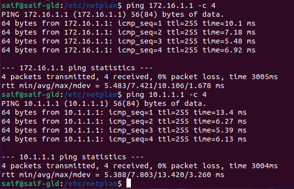
How about the routing table after adding the secondary IP in netplan ?
You can type the command ip route to see the routing table in ubuntu

As you can see there are two default routes one with the metric 20010 and other with 20100, and the traffic to other network or towards the internet would be via the gateway 172.16.1.1.
You can achieve the same result by keeping the netplan configuration first address with DHCP and second as static as well.
How to create Bond interface with VLAN tagged?

Sometimes , you may want to carry multiple VLAN on the same bond interfaces, that way you can separate each network into different broadcast domain.
To achieve the VLAN tagging on the interface, you can configure sub interface on the bond. Each sub interface indicate specific VLAN. For example, if wanted to create sub interface for the VLAN 20, the interface name should look like below.
Bond0.20
In this method, we are going to create Bond0 with a subinterface ( Bond0.10) that represents a VLAN tagged interface using netplan VLAN. And bond0 will act as the trunk.
1. Edit the netplan configuration file as below.
cd /etc/netplan/
sudo nano 01-network-manager-all.yaml
2. Group the interfaces.
Like above, group all the interfaces as one as eports here.
network:
 version: 2
 renderer: networkd
 ethernets:
     eports:
       match:
         name: ens*
3. Create netplan VLAN trunk.
In the netplan YAML file add the bond0 interface under bonds, just below that add the LACP parameters.
bonds:
   bond0:
     interfaces: [eports]
     dhcp4: no
     parameters:
       mode: 802.3ad
       mii-monitor-interval: 100
4. Create bond sub interfaces.
Create a VLAN with the VLAN blocks and name the VLAN as bond0.10.
The ID which represents the VLAN ID as 10, and You should also point the physical interface using the link then the IP addresses parameters.
vlans:
   bond0.10:
     id: 10
     link: bond0
     addresses: [10.1.1.10/24]
     gateway4: 10.1.1.1
     nameservers:
       search: [local]
       addresses: [4.2.2.2]
5. Validate the configuration.
The final netplan configuration would look like below.
network:
 version: 2
 renderer: networkd
 ethernets:
     eports:
       match:
         name: ens*
 bonds:
   bond0:
     interfaces: [eports]
     dhcp4: no
     parameters:
       mode: 802.3ad
       lacp-rate: fast
       mii-monitor-interval: 100
 vlans:
   bond0.10:
     id: 10
     link: bond0
     addresses: [10.1.1.10/24]
     gateway4: 10.1.1.1
     nameservers:
       search: [local]
       addresses: [4.2.2.2]
6. Apply the netplan configuration.
sudo netplan apply
7. Netplan verification.
As you can see the physical interface has become slave and the bond0 become the master. This time no IP address on the bond0
8: bond0: <BROADCAST,MULTICAST,MASTER,UP,LOWER_UP> mtu 1500 qdisc noqueue state UP group default qlen 1000
    link/ether a6:29:49:0c:2a:db brd ff:ff:ff:ff:ff:ff
    inet6 fe80::a429:49ff:fe0c:2adb/64 scope link
       valid_lft forever preferred_lft forever
- All the down below, You can also see the vlan interface as bond0.10 and it’s IP address as well.
9: bond0.10@bond0: <BROADCAST,MULTICAST,UP,LOWER_UP> mtu 1500 qdisc noqueue state UP group default qlen 1000
    link/ether a6:29:49:0c:2a:db brd ff:ff:ff:ff:ff:ff
    inet 10.1.1.10/24 brd 10.1.1.255 scope global bond0.10
       valid_lft forever preferred_lft forever
    inet6 fe80::a429:49ff:fe0c:2adb/64 scope link
- Lets ping from the switch to the IP of the vlan interface that we have created on ubuntu using netplan.
<GLD>ping 10.1.1.10
Ping 10.1.1.10 (10.1.1.10): 56 data bytes, press CTRL_C to break
56 bytes from 10.1.1.10: icmp_seq=0 ttl=64 time=1.447 ms
56 bytes from 10.1.1.10: icmp_seq=1 ttl=64 time=1.544 ms
56 bytes from 10.1.1.10: icmp_seq=2 ttl=64 time=1.842 ms
56 bytes from 10.1.1.10: icmp_seq=3 ttl=64 time=5.763 ms
56 bytes from 10.1.1.10: icmp_seq=4 ttl=64 time=1.542 ms
--- Ping statistics for 10.1.1.10 ---
5 packet(s) transmitted, 5 packet(s) received, 0.0% packet loss
round-trip min/avg/max/std-dev = 1.447/2.428/5.763/1.673 ms
<GLD>
Well, that worked just fine and our vlan interface is up and running.
How to tag multiple VLAN’s in a Bond using netplan?
In the last section, we configured the trunk interface using netplan but carrying only a single VLAN, VLAN 10.
In some scenarios, you might require multiple VLANs to be carried by the same physical link.
So let’s see how we can achieve the same using netplan, here we are going to configure the netplan VLAN trunk that carries vlan 10,20 and 30 like below.

1. Modify the Netplan configuration.
Last time, we had one VLAN interface, this time I am adding two extra configurations form VLAN 20 and 30.
Just copy and paste the same VLAN10 netplan configuration just below the VLAN 10 configuration and change the VLAN ID and IP address values like below.
network:
 version: 2
 renderer: networkd
 ethernets:
     eports:
       match:
         name: ens*
 bonds:
   bond0:
     interfaces: [eports]
     dhcp4: no
     parameters:
       mode: 802.3ad
       lacp-rate: fast
       mii-monitor-interval: 100
 vlans:
   bond0.10:
     id: 10
     link: bond0
     addresses: [10.1.1.10/24]
     gateway4: 10.1.1.1
     nameservers:
       search: [local]
       addresses: [4.2.2.2]
 vlans:
   bond0.20:
     id: 20
     link: bond0
     addresses: [10.2.2.10/24]
     gateway4: 10.2.2.1
     nameservers:
       search: [local]
       addresses: [4.2.2.2]
 vlans:
   bond0.30:
     id: 30
     link: bond0
     addresses: [10.3.3.10/24]
     gateway4: 10.3.3.1
     nameservers:
       search: [local]
       addresses: [4.2.2.2]
2. Apply the configuration.
apply the configuration by typing sudo netplan apply
3. Verify the configuration.
You can see the extra VLAN interfaces by typing ip addr command in Ubuntu.
VLAN 10
9: bond0.10@bond0: <BROADCAST,MULTICAST,UP,LOWER_UP> mtu 1500 qdisc noqueue state UP group default qlen 1000
    link/ether a6:29:49:0c:2a:db brd ff:ff:ff:ff:ff:ff
    inet 10.1.1.10/24 brd 10.1.1.255 scope global bond0.10
       valid_lft forever preferred_lft forever
    inet6 fe80::a429:49ff:fe0c:2adb/64 scope link
VLAN 20
15: bond0.20@bond0: <BROADCAST,MULTICAST,UP,LOWER_UP> mtu 1500 qdisc noqueue state UP group default qlen 1000
    link/ether a6:29:49:0c:2a:db brd ff:ff:ff:ff:ff:ff
    inet 10.2.2.10/24 brd 10.2.2.255 scope global bond0.20
       valid_lft forever preferred_lft forever
    inet6 fe80::a429:49ff:fe0c:2adb/64 scope link
       valid_lft forever preferred_lft forever
VLAN 30
14: bond0.30@bond0: <BROADCAST,MULTICAST,UP,LOWER_UP> mtu 1500 qdisc noqueue state UP group default qlen 1000
    link/ether a6:29:49:0c:2a:db brd ff:ff:ff:ff:ff:ff
    inet 10.3.3.10/24 brd 10.3.3.255 scope global bond0.30
       valid_lft forever preferred_lft forever
    inet6 fe80::a429:49ff:fe0c:2adb/64 scope link
       valid_lft forever preferred_lft forever
- Let’s ping these IP address from the switch to see if we are getting any response.
<GLD-SW11>ping 10.1.1.10
Ping 10.1.1.10 (10.1.1.10): 56 data bytes, press CTRL_C to break
56 bytes from 10.1.1.10: icmp_seq=0 ttl=64 time=1.254 ms
56 bytes from 10.1.1.10: icmp_seq=1 ttl=64 time=1.280 ms
56 bytes from 10.1.1.10: icmp_seq=2 ttl=64 time=1.254 ms
56 bytes from 10.1.1.10: icmp_seq=3 ttl=64 time=1.099 ms
56 bytes from 10.1.1.10: icmp_seq=4 ttl=64 time=1.173 ms
--- Ping statistics for 10.1.1.10 ---
5 packet(s) transmitted, 5 packet(s) received, 0.0% packet loss
round-trip min/avg/max/std-dev = 1.099/1.212/1.280/0.067 ms
<GLD-SW11>ping 10.2.2.10
Ping 10.2.2.10 (10.2.2.10): 56 data bytes, press CTRL_C to break
56 bytes from 10.2.2.10: icmp_seq=0 ttl=64 time=12.675 ms
56 bytes from 10.2.2.10: icmp_seq=1 ttl=64 time=1.466 ms
56 bytes from 10.2.2.10: icmp_seq=2 ttl=64 time=1.392 ms
56 bytes from 10.2.2.10: icmp_seq=3 ttl=64 time=1.057 ms
56 bytes from 10.2.2.10: icmp_seq=4 ttl=64 time=1.107 ms
--- Ping statistics for 10.2.2.10 ---
5 packet(s) transmitted, 5 packet(s) received, 0.0% packet loss
round-trip min/avg/max/std-dev = 1.057/3.539/12.675/4.571 ms
<GLD-SW11>ping 10.3.3.10
Ping 10.3.3.10 (10.3.3.10): 56 data bytes, press CTRL_C to break
56 bytes from 10.3.3.10: icmp_seq=0 ttl=64 time=1.507 ms
56 bytes from 10.3.3.10: icmp_seq=1 ttl=64 time=11.961 ms
56 bytes from 10.3.3.10: icmp_seq=2 ttl=64 time=3.114 ms
56 bytes from 10.3.3.10: icmp_seq=3 ttl=64 time=1.139 ms
56 bytes from 10.3.3.10: icmp_seq=4 ttl=64 time=13.636 ms
--- Ping statistics for 10.3.3.10 ---
5 packet(s) transmitted, 5 packet(s) received, 0.0% packet loss
round-trip min/avg/max/std-dev = 1.139/6.271/13.636/5.397 ms
<GLD-SW11>
As you can see it’s working as expected.
Grouping error in netplan
If you ever tried to configure bonding with the Ubuntu desktop using NetworkManager you might have seen the below error when you tried to group the interfaces.
networkmanager definitions do not support name globbing
To resolve this issue you can change the renderer from Network manager to networkd like below. If you apply the netplan now everything should work just fine.
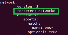
How do I tag VLAN on Ubuntu using Netplan?
The same way we configured the VLANs on the bond interface, you can configure the same on a single interface as well.
In the below diagram, we are going to take a look at ubuntu vlan configuration example where I have a Ubuntu box on the far right side, which is connected to a switch named sw2. Switch2 is configured with the VLAN and the default gateway is behind switch 2 on multiple devices on the far left side.
Basically, the layer2 switch doesn’t have any IP configuration and all the IP communication happens on the left side. For example, if Ubuntu host wanted to talk to the internet, it has to go via internet VLAN which VLAN 10 is located on the sw1 as 10.1.1.1 connected to the internet.
Similarly, if the Ubuntu host wanted to talk to the network 10.2.2.0/24 and 192.168.1.0/24 it has to be via VLAN 20 gateway 10.2.2.1.
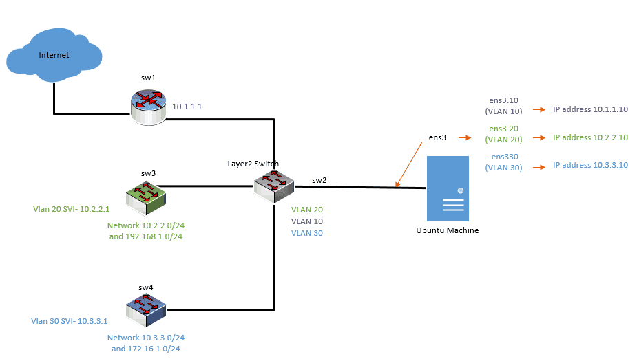
Let’s look at the potential Ubuntu VLAN configuration we have and we will start the configuration.
SW2 is connected to three different networks.
- SW1 on the left provides the access to the internet and it has the IP address of 10.1.1.1
- SW3 is providing network access to VLAN 20 and it has two internal networks 10.2.2.0/24 and 192.168.1.0/24.
- Finally, the SW4 has the VLAN 30 and the network 10.3.3.0/24 and 172.16.1.0/24.
I am using Ubuntu desktop 18.04 installed on a hypervisor. It has got the interface ens3.
To represent VLAN tagged interface, we need to create a sub-interface from the physical interface ens3.
Let’s go ahead and configure the VLAN interfaces from this physical interface.
You can see the representation of the subinterface on the right side.
1. Creation of sub interfaces to represent the VLAN’s in Ubuntu.
Go to etc/netplan and edit the netplan configuration files to add the VLAN interfaces.
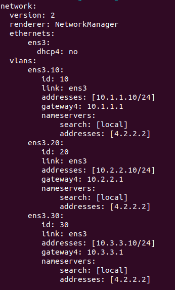
- First block look like below, where you have the version, renderer and ethernets are defined.

Lets go ahead and add the vlan interfaces one by one.
- For VLAN 10
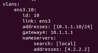
- For VLAN 20
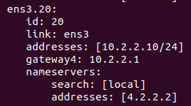
- For VLAN 30
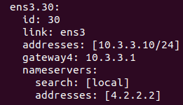
- The final Ubuntu VLAN Configuration would look like below.
2. Apply the configuration.
Apply the configuration with sudo netplan apply the command.
3. Verification
We just configured the Ubuntu VLAN interfaces using netplan, to verify the configuration that you just made, Enter the command ip addr
As you can see below both the physical interface as well as VLAN subinterfaces. Awesome!
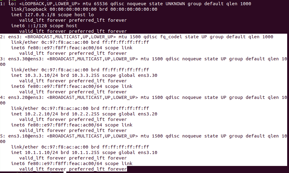
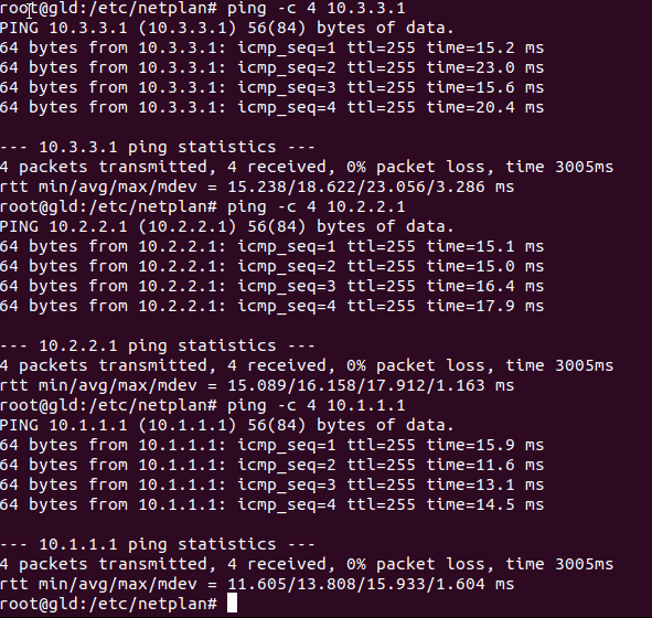
Ping each VLAN gateways to make sure it is able to talk to the network.
As you can see I am able to ping all the three VLAN gateways from my Ubuntu machine.
Getting an error while applying the configuration?
In the above scenario, everything worked just fine, however in some of the scenarios, when you try to create VLAN interfaces using Netplan, it wouldn’t come up.
Every time when I try to apply the config, it would show the below error message.

That’s because you have not applied the configuration properly.
Note: This is a different scenario, not the same example as before. here I am using VLAN 100 and 200.
Before the change.
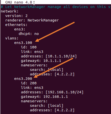
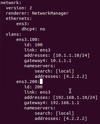
If you look into it there is no column on the VLAN interface. let’s add that and that should fix the issue.
After the change.
Apply the config, now if you check the IP address configuration, it should reflect the new VLAN IP addresses.
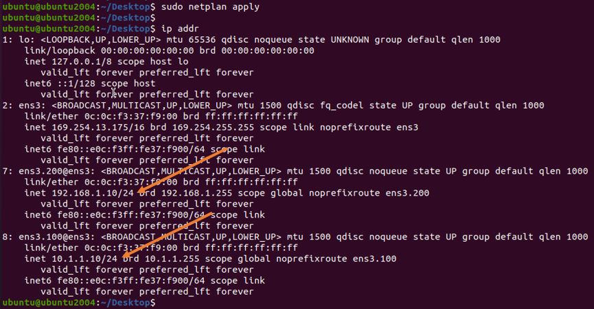
Let’s also verify by pinging the IP address.
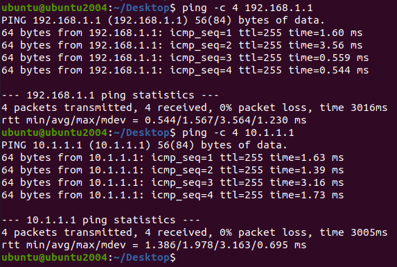
As you can see, all the VLANs are working fine.
