
In our last blog post, we covered how you can install a FortiGate firewall in GNS3, and in this blog, we are going to continue from where we left off to build a lab with the FortiGate firewall.
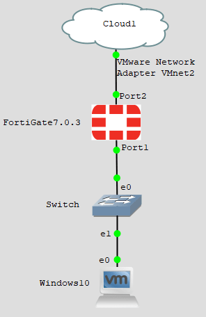
Below is the topology that we are going to build.
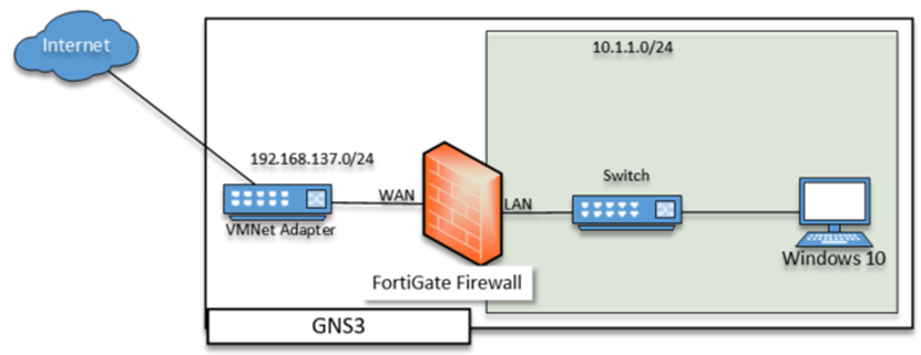
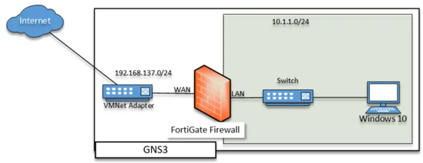
The FortiGate firewall WAN interface is connected to the internet, and the LAN side is connected to a switch serving the LAN traffic. The LAN users will go out to the internet using the FortiGate firewall at the end of the configuration. You can further expand the lab by adding multiple FortiGate firewalls using IPsec VPN to simulate the branch connectivity, which we will cover in a later blog post.
Prerequisites,
Before proceeding with the lab, you need to ensure that you have downloaded and installed the FortiGate firewall on your Gns3. If you have not done that, you may go back to the article here, complete the installation and proceed with the lab.
I am using GNS3 on a remote server. However, the steps mentioned here are identical if you use the GNS3VM.
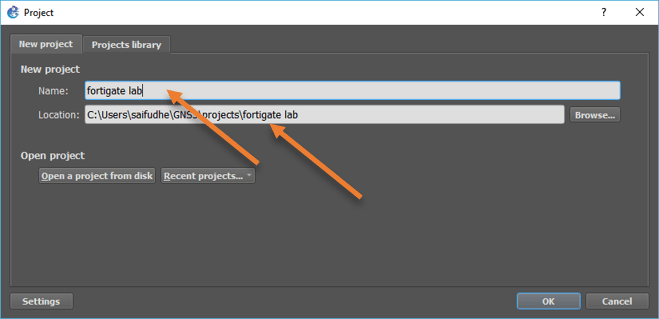
1. Create a new project in GNS3.
We have successfully installed the FortiGate on GNS3. Let’s go ahead and spin up a small lab.
When you add the FortiGate firewall to the gns3, it will have ten virtual interfaces added to it. However, we don’t require all ten interfaces for this LAB. We could use port 1 for the LAN network plus the management network. Port2 for the internet connection. In production, you must have a LAN and the management interface separate.
- In GNS3, click on the file and click new blank project.
- Provide a project name and the location where you want to keep the project files and click on Ok.

2. Configure the FortiGate.
We will configure and prepare the FortiGate firewall, and when we are ready, we will plug in each port.
Power on the firewall.
Drag and drop the firewall to the topology, right-click on it and click on Start.
After a few seconds, the firewall will be loaded and ask for the username.
Set the password for the firewall.
You may enter the username as admin, leave the password blank, and enter.
You will be asked to set up a password for your FortiGate firewall, enter the new password and confirm the new password. After that, you will be able to log in to the FortiGate virtual machine using the username admin and the password you just created.
FortiGate-VM64-KVM login: admin
Password:
You are forced to change your password. Please input a new password.
New Password:
Confirm Password:
Welcome!
Configure the port1 IP and enable http access.
We will need to configure the IP address on the LAN interface. That way, we can access the web GUI using the LAN IP. By default, the FortiGate firewall will have HTTPS access enabled for management purposes on port1. However, you cannot use the web GUI using HTTPS Because we are running a trial license that will be valid only for 16 days, hence you need to enable http on the port1.
You can type show system interface port1, and you can see the port one is enabled with ping https ssh fgfm.
FortiGate-VM64-KVM # show system interface port1
config system interface
    edit "port1"
        set vdom "root"
        set mode dhcp
        set allowaccess ping https ssh fgfm
        set type physical
        set snmp-index 1
    next
end
FortiGate-VM64-KVM #
Configure the IP address and role.
Port 1 of the firewall is enabled with static mode, however, no IP address is configured. We are going to configure 10.1.1.1/24 on the LAN port of the firewall, also make the role for the LAN port as LAN.
Config system interface
Edit port1
set mode static
set ip 10.1.1.1 255.255.255.0
  set role lan
Configure the http access.
Follow the below commands to enable http access on port1.
config system interface
    edit "port1"
        set allowaccess ping http ssh fgfm
    next
end
Note: You have to make sure that you add all the ports you want, if you just add http, other protocols will be removed.
Verify the configuration on port1.
Before you proceed, verify the configuration on port1, by typing the command show system interface port1.
FortiGate-VM64-KVM # show sys int port1
config system interface
    edit "port1"
        set vdom "root"
        set ip 10.1.1.1 255.255.255.0
        set allowaccess ping ssh http fgfm
        set type physical
        set role lan
        set snmp-index 1
    next
end
Configure the FortiGate port2 for WAN.
We will use the DHCP service on the WAN side of the firewall and by default, it is not configured as you can see below.
FortiGate-VM64-KVM # show system interface port2
config system interface
    edit "port2"
        set vdom "root"
        set type physical
        set snmp-index 2
    next
end
FortiGate-VM64-KVM #
Configure it to use for DHCP.
config system interface
config system interface
 edit "port2"
 set mode dhcp
 set role wan
end
That’s it we have completed the firewall side of the configuration, let’s go ahead and plug in the firewall and proceed with the rest of the configuration.
3. Connect port1 to the LAN side.
Connect the port1 to any of the LAN machines. You could use a Linux or Windows host as a LAN machine, I am using windows 10 connected to the LAN side. Do not use CLI only device because we need to access the firewall GUI using the LAN side host.
Set the IP address on the LAN host.
We need to configure the LAN host to communicate with the firewall LAN side, for that it has to be part of the 10.1.1.0/24 network. Configure any IP address from that subnet, and you should be able to reach the firewall LAN side.
C:\Users\Saif>ipconfig
Windows IP Configuration


Ethernet adapter Ethernet:

   Media State . . . . . . . . . . . : Media disconnected
   Connection-specific DNS Suffix  . :

Ethernet adapter Ethernet0 2:

   Connection-specific DNS Suffix  . :
   Link-local IPv6 Address . . . . . : fe80::989d:fe94:acd4:5fab%14
   IPv4 Address. . . . . . . . . . . : 10.1.1.10
   Subnet Mask . . . . . . . . . . . : 255.255.255.0
   Default Gateway . . . . . . . . . : 10.1.1.1

Ethernet adapter Bluetooth Network Connection:

   Media State . . . . . . . . . . . : Media disconnected
   Connection-specific DNS Suffix  . :


C:\Users\Saif>ping 10.1.1.1

Pinging 10.1.1.1 with 32 bytes of data:
Reply from 10.1.1.1: bytes=32 time=3ms TTL=255
Reply from 10.1.1.1: bytes=32 time=2ms TTL=255
Reply from 10.1.1.1: bytes=32 time=2ms TTL=255
Reply from 10.1.1.1: bytes=32 time=5ms TTL=255

Ping statistics for 10.1.1.1:
    Packets: Sent = 4, Received = 4, Lost = 0 (0% loss),
Approximate round trip times in milli-seconds:
    Minimum = 2ms, Maximum = 5ms, Average = 3ms

C:\Users\Saif>
I can reach the firewall via ICMP. We can ping because we already allowed ping on the LAN side.
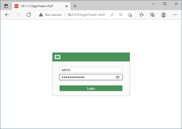
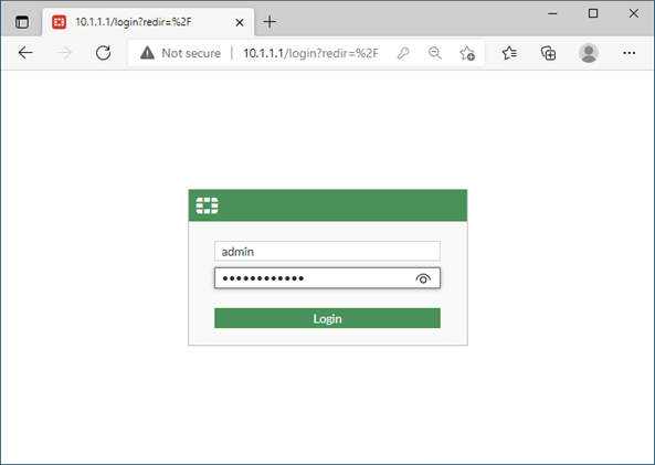
Access the Web gui.
You may type http://10.1.1.1 on your LAN host to access the web GUI of the firewall.
Enter the username and password that you set before.
Note: Do not try to access the GUI using HTTPS. Since we don’t have license you cannot access it, and moreover, we removed the HTTPS from the port configuration.
After you sign in, you will get FortiGate Setup. You may click on Later.
Configure the DHCP service on the LAN.
We have set the IP address of the windows machine statically, but that’s not the right way you manage the IP address on the LAN side. Instead, we either need to use a DHCP server or enable DHCP service on the LAN port.
On the GUI->Network->Port1-> Double click on it.
Scroll down and check the box for the DHCP server.
I am leaving all the settings default. You could change the address range if you want to.
If you require to send more DHCP options that is available under advanced, which we are not going to do now.

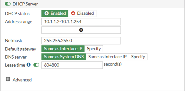
After the configuration click on Ok.
Click on OK again on the prompt.
Verify the DHCP service.
At this point in time, you either can add another host with DHCP enabled to connect to the firewall LAN side or remove the static IP on the Windows host and will allow it for DHCP.
Though I could connect to another host, I will switch the windows ip address to DHCP.
After I made the changes, as you can see, the windows host got an IP address 10.1.1.2 from the FortiGate DHCP service. The DNS servers that you see are from the FortiGate firewalls.
Ethernet adapter Ethernet0 2:

   Connection-specific DNS Suffix  . :
   Description . . . . . . . . . . . : Intel(R) PRO/1000 MT Network Connection
   Physical Address. . . . . . . . . : 00-0C-29-4E-E7-46
   DHCP Enabled. . . . . . . . . . . : Yes
   Autoconfiguration Enabled . . . . : Yes
   Link-local IPv6 Address . . . . . : fe80::989d:fe94:acd4:5fab%14(Preferred)
   IPv4 Address. . . . . . . . . . . : 10.1.1.2(Preferred)
   Subnet Mask . . . . . . . . . . . : 255.255.255.0
   Lease Obtained. . . . . . . . . . : Thursday, January 6, 2022 3:45:29 AM
   Lease Expires . . . . . . . . . . : Thursday, January 13, 2022 3:45:29 AM
   Default Gateway . . . . . . . . . : 10.1.1.1
   DHCP Server . . . . . . . . . . . : 10.1.1.1
   DHCPv6 IAID . . . . . . . . . . . : 436210729
   DHCPv6 Client DUID. . . . . . . . : 00-01-00-01-27-A2-AA-3E-00-0C-29-4E-E7-46
   DNS Servers . . . . . . . . . . . : 208.91.112.53
                                       208.91.112.52
   NetBIOS over Tcpip. . . . . . . . : Enabled
4. Connect firewall to the internet.
We have configured the LAN side of the firewall, and when you add more and more hosts, the FortiGate firewalls will start acting as DHCP servers and hand out the IP addresses. But those hosts cannot go out to the internet because we have not connected the firewall to the internet. After all, we are waiting for the ISP to provide public internet connectivity 😀
let’s go ahead and do that.
Connect a cloud to port2 for internet access. You can read this article to know how to configure internet access on gns3 using the cloud.

As soon as the cloud was plugged into the WAN port of the firewall, I got an IP address from the DHCP server (second line).
FortiGate-VM64-KVM # diagnose ip address list
IP=10.1.1.1->10.1.1.1/255.255.255.0 index=3 devname=port1
IP=192.168.137.197->192.168.137.197/255.255.255.0 index=4 devname=port2
IP=127.0.0.1->127.0.0.1/255.0.0.0 index=13 devname=root
IP=10.255.1.1->10.255.1.1/255.255.255.0 index=17 devname=fortilink
IP=127.0.0.1->127.0.0.1/255.0.0.0 index=18 devname=vsys_ha
IP=127.0.0.1->127.0.0.1/255.0.0.0 index=20 devname=vsys_fgfm

FortiGate-VM64-KVM #
Since we acquired the IP address via DHCP, it will also have the default gateway configured that will act as a default route for the firewall, so when you try to ping the internet, you should get a response.
FortiGate-VM64-KVM # execute ping 8.8.8.8
PING 8.8.8.8 (8.8.8.8): 56 data bytes
64 bytes from 8.8.8.8: icmp_seq=0 ttl=115 time=21.1 ms
64 bytes from 8.8.8.8: icmp_seq=1 ttl=115 time=22.3 ms
64 bytes from 8.8.8.8: icmp_seq=2 ttl=115 time=22.2 ms
64 bytes from 8.8.8.8: icmp_seq=3 ttl=115 time=22.4 ms
64 bytes from 8.8.8.8: icmp_seq=4 ttl=115 time=21.4 ms

--- 8.8.8.8 ping statistics ---
5 packets transmitted, 5 packets received, 0% packet loss
round-trip min/avg/max = 21.1/21.8/22.4 ms

FortiGate-VM64-KVM #
Note: In case you have configured the IP address statically, you will also need to configure the default route for the firewall.
5. Configure FortiGate LAN side for internet access.
Internet access is now available to the firewall. Still, you must configure the security policy and the NAT configuration for the LAN host to go out to the internet using the FortiGate internet link.
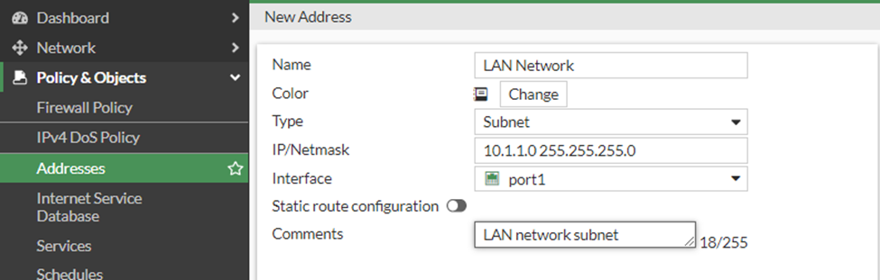
Add the LAN address object.
While creating the Policy, we need to call the LAN interface subnet to the Policy, so it is better to keep the address object ready before proceeding with the policy creation.
Policy&Objects-> Addresses->Create New->Address.
Name : LAN Network.
Type : Subnet
IP/Netmask : 10.1.1.0 255.255.255.0
Interface : Choose the LAN port, which is port1
Enter a command and click on Ok.

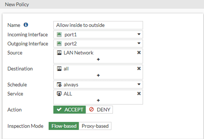
Configure the Policy for internet.
We will create a policy to allow inside users to go out to the internet.
Policy&Objects -> Firewall Policy-> Create New.
Name : Allow inside to Outside.
Incoming interface: All the traffic will be coming from the LAN side, hence choose port1.
Outgoing interface: The egress traffic for the internet is Port2.
Source: We already created the address object for the source, the LAN network.
Destination: All.
Schedule: Leave the default which is always.
Action: Allow.
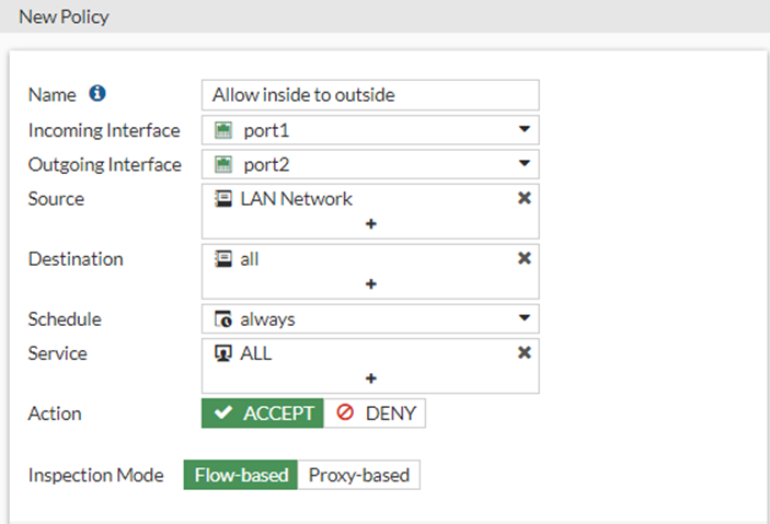
Create NAT policy.
The security policy is to allow the traffic from inside to outside, but when the traffic leaves from the LAN it would be a private IP address, and when it has to go out, the Ip address should get translated to a public IP address. Hence we need to configure the NAT on the same security Policy.
Scroll down.
Under Firewall/Network Options, check the NAT option
IP Pool configuration: Use Outgoing interface address
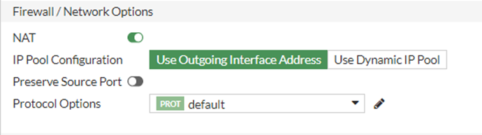

Note: Here we are using Private IP on the WAN side of the firewall, so when the private IP 192.168.137.0/24 go out from the firewall, it gets again translated to the host IP address, and the host IP address get translated to my router WAN IP address and then go to the internet, it’s crazy when you think about it, but that’s how it works.
You can also enable the security profile; however for the LAB the above configuration should be enough.
To see the logs for each traffic, you may check the LogAllowedTraffic, and choose All sessions.

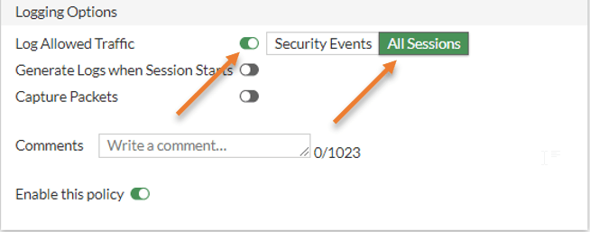
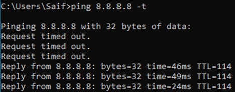
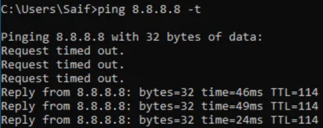
Before you click on OK, you may start pinging any public IP from your LAN host, and as soon as you apply the configuration, you should get a response.
I clicked on Ok, and as you can see, I am getting a response for my ping, which is fantastic.
You may check the traceroute, and you should see the traffic is going through your firewall.
C:\Users\Saif>ping www.google.com

Pinging www.google.com [142.250.67.36] with 32 bytes of data:
Reply from 142.250.67.36: bytes=32 time=22ms TTL=114
Reply from 142.250.67.36: bytes=32 time=20ms TTL=114
Reply from 142.250.67.36: bytes=32 time=21ms TTL=114
Reply from 142.250.67.36: bytes=32 time=22ms TTL=114

Ping statistics for 142.250.67.36:
    Packets: Sent = 4, Received = 4, Lost = 0 (0% loss),
Approximate round trip times in milli-seconds:
    Minimum = 20ms, Maximum = 22ms, Average = 21ms

C:\Users\Saif>tracert www.google.com

Tracing route to www.google.com [142.250.67.36]
over a maximum of 30 hops:

  1   177 ms     5 ms     2 ms  10.1.1.1
  2    65 ms     *        4 ms  192.168.137.1
  3     *        *        *     Request timed out.
  4     8 ms     5 ms     7 ms  192.168.0.1
  5    85 ms     7 ms     9 ms  100.65.128.1
^C
C:\Users\Saif>
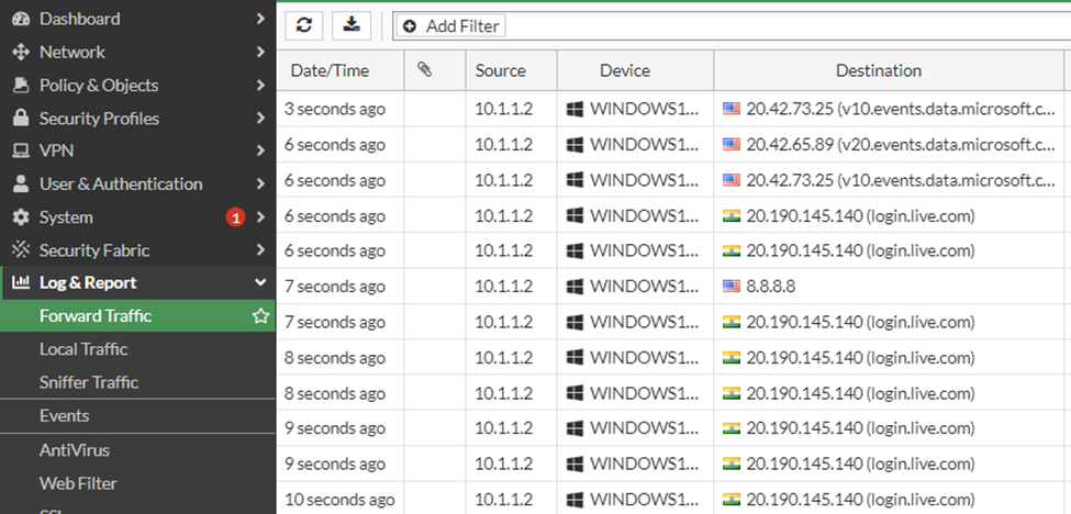
You can also see the logs in Log%Report-> Forwarded Traffic, to see all the traffic that was initiated from the windows host that we connected to the firewall.

We have successfully implemented the FortiGate firewall lab on GNS3, and you can further expand this lab from here and configure IPsec VPN, HA configuration, port forwarding, etc. The more you get your hands dirty, the better you understand the technology.