

You have got the brand new Paloalto firewall installed, and have been told to set up an IPsec site to site VPN between branches, and you are new to the paloalto firewall, what should you do ?
No worries, you came to the right place.
If I were to configure an IPSec tunnel for the first time, I would configure them in my lab before I configure it in production.
That way, I would be well prepared before I implement them in the production.
The great thing about the Paloalto firewall is that you can spin up its VM appliance in any of the hypervisors and it supports most of the features for you to get started.
You could even spin them up in gns3 or EVE-NG, in fact the lab I am using for this demo, I have set it up in gns3.
If you got a VM appliance, there are some features that may not work well with an unlicensed version. Still, for the lab purpose with basic routing and IPsec connectivity the unlicensed version is still good.
If you are into getting a license for the Paloalto vm for 60 days, that’s even better.
you can reach out to your account manager, or click on the link below to request one.
This is an updated blog article, so the topology that I have used in the previous labs, are no longer the same.
So in case you came to this page, with the bookmarked link, you got a different lab now 🙂
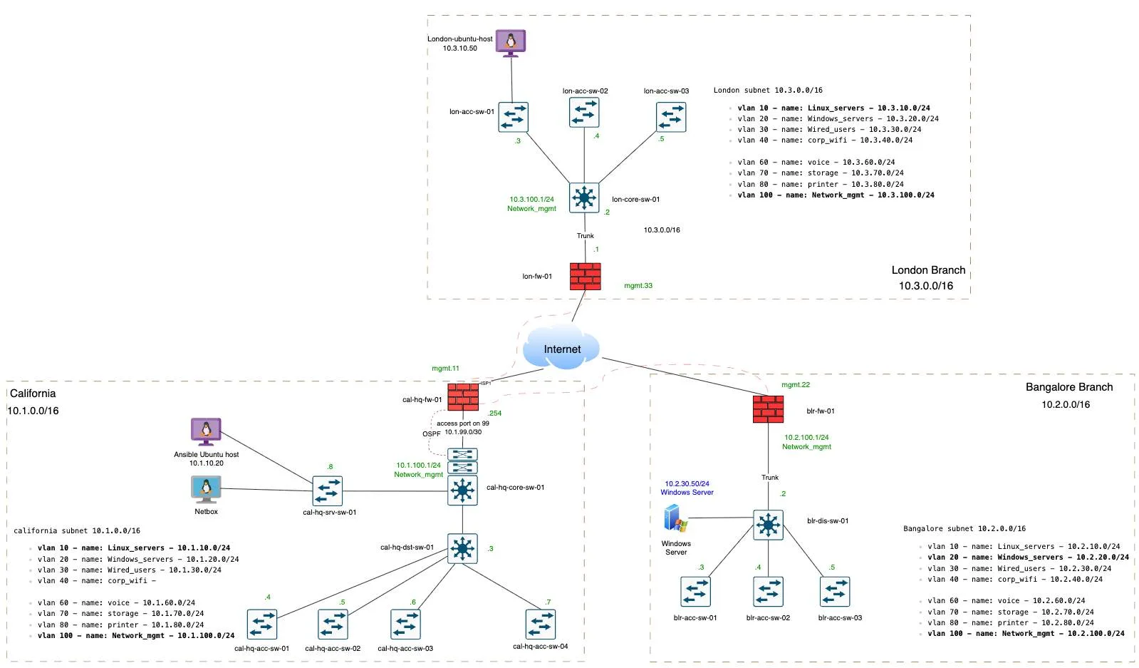
So below is the topology that I am going to work on, I have got two three sites. One is in California we call it CAL-HQ, that’s the headquarters on the left, and we have branches in Bangalore , BGL for short on the right and in London as well which is at the top.

In this article we will not connect all the sites, instead focus between california hq and the bangalore branch.
Don’t worry too much about London for now.
Once that is done, we would then create a hub and spoke topology, same shown in the topology, where the cal-hq will act as hub, and if London and Bangalore wanted to talk, it has to come via California.
After completing this blog, you will have a IPsec connectivity between california and bangalore and we will ensure both side end devices can communicate with each other.
I am using a linux host to test in california, whereas in bangalore, I am using a windows machine.
Before we get started, it’s important to note down the configuration parameters that we would be using.
| CAL-HQ | BGL | |
| LAN-Network | 10.1.0.0/16 | 10.2.0.0/16 |
| Public IP | 1.1.1.154 | 2.2.2.13 |
| Phase1- DH group, Encryption and Authentication | Group14/AES256CBC/Sha256 | |
| Phase2 – Encryption, DH Group and Authentication | AES256/Sha256/Group14 | |
| Pre-shared key | Add a strong pre-shared key that matches on both the locations, I am using a 20charector key with alpha numeric. | |
If you prefer to watch step by step video, you can watch the video here 👇
California HQ Palo Alto IPsec Configuration.
We will configure the california site, and then we will proceed with the bangalore one. So before diving into the IPsec tunnel configuration, it’s important to create a network object with the subnet that represents each site, that will save a ton of time.
Add Network Object.
From the table above, we know the network that we would be using is 10.1.0.0/16 for the whole california site, although many of the deployment for small branches you would see /24 or /22 subnets, but we are sticking with the whole /16 so that we don’t miss out on the smaller subnets behind california hq.
You could still configure the IPsec tunnel without having this object, but creating this object will not only standardise your setup, but also saves a ton of time when dealing with configuration and troubleshooting.
To create an object click Object tab, and click on Addresses
Click on Add to add a new object.
In the name you can add remote network name and the subnet, in our example
Bgl subnet, so I am naming it like this ‘bgl_sub_10.20.0.0_16’ and the type is IP netmask and the address is 10.2.0.0/16

So I have added both the subnets now.

Create IPsec parameters.
When dealing with the IPsec configuration, you have to configure phase1 of the tunnel that takes care of the public IP communication encryption and authentication, and using that we built a phase2 tunnel on top of it, to encrypt the data.
You can go to Network and under Network profiles, you can start with the phase1 configuration and then move on to phase2.
IPsec phase1 configuration.
The phase1 deals with IKE Crypto and IKE gateway
Configure IKE Crypto.
In Network -> Network Profiles on the left-> click on IKE crypto and click on Add.

Name: Enter a user-friendly name.
DH group: Group14.
Encryption: aes-256-cbc
Authentication: sha256
That’s all you have to do, and click on ok.

Configure IKE-Gateway.
Now click on the IKE-gateway, and click on add.

Name: Enter the name, I am following the same sequence I have used previously.
Version: Choose IKEv2 only mode.
Interface: choose your WAN interface where the public IP is configured.
Local IP address: from the drop down choose the local IP.
Peer address: Enter the remote branch IP, in our case BGL IP which is 2.2.2.13
Pre-Shared Key: Enter the key that is strong.
You may now click on Advanced Options.

Here, if you choose the following:
Enable Passive mode: the IPsec will not initiate the tunnel, only when the remote initiates the tunnel it will respond, so we don’t want that, so I am not checking this option.
Enable NAT traversal: If your Paloalto is behind a NAT device like an ISP router, and you don’t have public IP configured directly on the firewall, then you can choose this option.
With this IPsec will be initiated on UDP port 4500, else it will be on 500.
I am not checking this as well.
IKE Crypto profile: In the crypto profile choose the IKE crypto that we generated in our last step, and click on ok.

IPsec Phase2 configuration.
The phase2 deals with the IPsec crypto, so above the IKE crypto, click on IPsec crypto.

Click on Add to add new IPsec crypto.
Name: Enter a name.
Encryption: Choose AES256
DH Group: Group14
Authentication: Sha256
Click ok.

Add Tunnel interface.
We are now going to create a tunnel interface where these parameters are going to be applied.
Click on Network -> Interfaces -> Tunnel.
And click on Add.

Interface: Add a number that represents the tunnel.
Under config:
Virtual router: choose the virtual router you have, if you have brand new palaolto device, it would be named as ‘default’
Security Zone: Since I don’t have a zone specific to IPsec, let me create one, by click on New from the drop down.

In the Zone creation pop up, I will add a zone named IPsec and click on Ok.

Ensure to choose IPsec as the tunnel interface zone.
You don’t have to configure any IP address for this tunnel, unless you are planning to configure some dynamic routing.
Ensure to add a comment to identify the tunnel easily.
And click on ok.

Build an IPsec tunnel with all the parameters.
With all the 4 Parameters we defined, we will now create an IPsec tunnel.
Under Network, click on IPsec tunnels, and click on add to add new tunnel.

Name: Enter a name for the iPSec tunnel.
Tunnel Interface: Choose the tunnel we created.
IKE Gateway: Choose the IKE gateway we created.
IPsec Crypto Profile: CHoose the IPsec crypto profile we defined.
And click on OK.

You can see, the tunnel is now created, and it is currently down.
The tunnel info is the phase2 and IKE info is the phase1, so this will be an indication where the problem is.
Sometimes, you will notice that Phase1 is up, however phase2 is down.

Update the IPsec routing table at California Site.
We built the tunnel, and we have to tunnel the firewall to send all the traffic destined to Bangalore via tunnel1.
For that we would have to create a static route, you could achieve the same using other dynamic routing protocols as well. That is covered over here.
In the network, click on virtual routers.
And click to open the virtual router.
In that click on static routes.
Name: Enter the name of the route.
Destination: Choose the object that we defined earlier.
Interface: Choose the tunnel interface.
Next hop: None, you don’t have to add any IP address here.
Don’t worry about the Path monitoring, this can be utilised when you have multiple tunnels.
And click on ok.

Create Paloalto security Policy.
We have routed the traffic and by default, it will be blocked by the firewall, so you need to create an outbound policy to allow the traffic.
Define outbound policy.
In policies, Security.
Click on Add to add a new policy.
Under General:
Name: Enter a name to identify the policy.
Source Zone: Inside, because we are allowing the traffic initiated from the California firewall LAN side.
Source Address: Chose the california address object we defined.
Click on Destination.

Destination Zone: We are directing the Bangalore traffic to the IPsec zone, hence choosing IPsec.
Destination Address: we want to only talk to the Bangalore subnet so choose that object.
You can play around with the applications, services and things like that, but since it’s a lab, I am not touching any of that and I am allowing all.
In Actions tab, ensure to choose action Allow.

Define inbound policy.
I am not going to create an inbound policy yet, because many people get confused that they need to have both inbound and outbound policy to be open for the traffic to work.
In fact since the firewall is a stateful one, whatever traffic initiated from California lan side, will be allowed because of the outbound policy that we defined, and the return traffic for the same session will be allowed, only if it’s for the same traffic.
However the traffic initiated as new from bangalore by default will be blocked, for which we need to create an inbound policy, which will do after the test.
And commit the changes.
Configure the IPsec site to site tunnel at bangalore Paloalto Firewall.
Lets head over to bangalore and define the bangalore side. I am not going to mention each and every minute details here, as we already did so while ocnfiguring the california paloalto firewall.
Configure the network Object
Like we did with the california site, lets create an object for bangalore site.
Create IKE crypto.
Defined the IKE crypto that is matching the california site, just the name is different.
Click on ok.

Create an IKE gateway.
In the IKE gateway, everything looks the same, except the following.
The local IP address and the peer IP address will be interchanged.

Also ensure to choose IKE-crypto profile in the advanced options.
And click on ok.

Configure the tunnel interface like we did before, with the IPsec zone.

Configure the IPsec tunnel.
We have configured the IKE crypto, IKE gateway, and IPsec crypto and tunnel interface, we are going to call this in the IPsec tunnel.
So click on IPsec tunnel, and click on add.
Name: Enter the name of your choice.
Tunnel interface: Choose the tunnel interface that we created.
IKE Gateway: Choose the IKE gateway that we created.
IPsec crypto profile: Choose the profile that we defined.
Click on ok.

The IPsec tunnel is now showing down.
Because we have not committed yet.

Update the static route.
Goto virtual router -> Static routes
Click on Add to add the static route.
Add the routes towards the opposite side, this time towards the California network which is 10.1.0.0/16.
Click ok.

Configure Inbound Security Policy.
Configure the security policies for the traffic that is coming from California to Bangalore.
In the security policy, click on Source.
Source Zone: Choose IPsec – because traffic will be initiated from California.
Source Address: and california subnet.

In the destination
Destination zone: choose inside.
Destination address: choose Bangalore inside subnet which is 10.2.0.0/16
Action should be allowed and click on Ok.

And commit the changes.
Alright, we have configured the tunnel at both sides, and the traffic from california to the bangalore site is now allowed.
Lets test the Ipsec tunnel.
Test the IPsec connectivity.
Let me go to the Host in california and test the connectivity, I am pinging the windows server in VLAN 30 on bangalore firewall lan side.
As you can see, it is responding fine.
Dont worry about the latency, it’s not that far in my lab 🙂

However if you ping the other way around it doesn’t work, meaning, if I try to ping from bangalore to california it never works, because we have not created a policy for it. Remember we skipped one policy ?

Create an outbound policy in Bangalore.
In the policy chose the following.
Source Zone: Choose the zone as Inside, that’s where the Bangalore subnets are.
Source Address: Bangalore subnet 10.2.0.0/16

Destination zone: IPsec – cos that where it should go reach california subnet.
Destination Address: California Address.

Create an inbound policy at the California firewall.
In the policy create a new policy with the following.
Name: Enter a name.
Source zone: IPsec
Source Address: Bangalore subnet.

Destination zone: Inside
Destination address: California address.

And commit the changes.
And Hurray, As in when the commit reached to 98% the traffic is now responding in my windows machine.
