
Quick Answer / CLI Template (HQ Side) If you are an experienced engineer and just need the syntax for your specific topology, here is the complete CLI block for the HQ Firewall.
# --- Phase 1: Define the Tunnel Interface ---
config vpn ipsec phase1-interface
    edit "HQ_to_Branch01"
    set interface port1
    set ike-version 2
    set local-gw x.x.x.24
    set remote-gw x.x.x.103
    set psksecret "your_strong_pre_shared_key"
    set proposal aes128-sha256
    set dhgrp 5
    set nattraversal disable
    next
end

# --- Phase 2: Define Subnets (Selectors) ---
config vpn ipsec phase2-interface
    edit "HQ_Sub_01_Br_Sub_01"
    set phase1name "HQ_to_Branch01"
    set proposal aes256-sha256
    set dhgrp 5
    set src-subnet 10.1.1.0 255.255.255.0
    set dst-subnet 10.2.2.0 255.255.255.0
    next
    edit "HQ_Sub_01_Br_Sub_02"
    set phase1name "HQ_to_Branch01"
    set proposal aes256-sha256
    set dhgrp 5
    set src-subnet 10.1.1.0 255.255.255.0
    set dst-subnet 10.200.200.0 255.255.255.0
    next
end

# --- Routing: Point Traffic to Tunnel ---
config router static
    edit 2
    set dst 10.2.2.0 255.255.255.0
    set device "HQ_to_Branch01"
    next
    edit 3
    set dst 10.200.200.0 255.255.255.0
    set device "HQ_to_Branch01"
    next
end
(Scroll down for the detailed explanation, Policy configuration, and Branch-side steps)
Introduction
We have set up IPsec site-to-site VPNs using the FortiGate Web GUI many times. However, sometimes you may not have access to the Web GUI (e.g., during a remote recovery or low-bandwidth situation), so the only option is to build the IPsec tunnel and route traffic using the Command Line Interface (CLI).
Setting up a VPN using the FortiGate CLI is fast, but it requires precision. If you are not careful, it is highly likely you could overwrite an existing configuration.
⚠️ Critical Warning: Before pasting the routing commands above, always check your existing routes by running show router static
- If you use edit 2 but Sequence Number 2 already exists, you will overwrite that route.
- Always pick an unused Sequence Number.
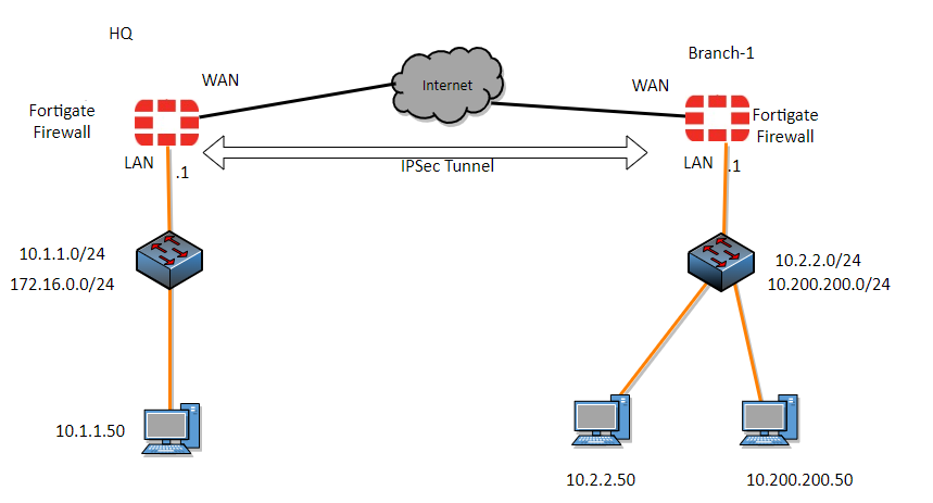
Topology Overview
In this guide, we are configuring a VPN between:
- HQ Firewall: WAN (x.x.x.24) | LAN (10.1.1.0/24)
- Branch Firewall: WAN (x.x.x.103) | LAN (10.2.2.0/24) & (10.200.200.0/24)

Steps to configure IPsec site to site VPN tunnel using CLI in fortigate.
We will start the configuration at the HQ site and then we will move on to the branch location.
1. Configure Phase1 of the IPsec tunnel in HQ.
We will start with the phase1 of the configuration and then we will proceed with the phase2.
We are going to configure the phase1 of the tunnel with IKEv2 and aes128 encryption algorithm and sha256 for the Authentication.
Important things to keep in mind.
- The name of the tunnel should be unique, it should not be the same as the other tunnel, if you leave the name same as the other tunnel it will replace the existing tunnel configuration.
- set your public IP in the local gateway, and the remote gateway as the remote public IP.
- set your own pre-shared key, it is important to keep it strong.
config vpn ipsec phase1-interface
    edit HQ_to_Branch01
        set interface port1
        set ike-version 2
        set local-gw x.x.x.24
        set proposal aes128-sha256
        set dhgrp 5
        set nattraversal disable
        set remote-gw x.x.x.103
        set psksecret your_strong_pre_shared_key
    next
end
2. Configure Phase2 of the IPsec tunnel in HQ.
In the phase2 configuration, we need to define the subnet that we are going to use for the communication.
In HQ we have the subnet 10.1.1.0/24 and the remote has two subnets 10.2.2.0/24 and 10.200.200.0/24, so we need to define two subnets in phase2 selectors.
it is important that you match the name of the phase1name in the previous phase1 configuration.
config vpn ipsec phase2-interface
    edit HQ_Sub_01_Br_Sub_01
        set phase1name HQ_to_Branch01
        set proposal aes256-sha256
        set dhgrp 5
        set src-subnet 10.1.1.0 255.255.255.0
        set dst-subnet 10.2.2.0 255.255.255.0
    next
    edit HQ_Sub_01_Br_Sub_02
        set phase1name HQ_to_Branch01
        set proposal aes256-sha256
        set dhgrp 5
        set src-subnet 10.1.1.0 255.255.255.0
        set dst-subnet 10.200.200.0 255.255.255.0
    next
end
3. Configure the IPsec static route in CLI.
Before you proceed with static route configuration in cli, it is best to check the current static route configuration so that we won’t erase the existing route configuration.
To check the current route configuration you could issue the command show router staticIt will list down all the static route including the sequence number, so it is important that you define the static route with unused sequence number otherwise you will erase the existing static route on your firewall.
In my case, I can see, I have a lab firewall which has only a default route towards the internet, it has the sequence number of 1, so I could use number 2.
So in production, you may have hundreds of routes, so better to run the show router static command and get the sequence number that was never used.
config router static
    edit 2
        set dst 10.2.2.0 255.255.255.0
        set device HQ_to_Branch01
    next
    edit 3
        set dst 10.200.200.0 255.255.255.0
        set device HQ_to_Branch01
    next
end
4. Configure Security policy in FortiGate IPsec in CLI
We have defined the routes for the traffic to exit, but the firewall will by default will block the traffic going to and from the ipsec, to ensure the traffic passing through the ipsec tunnel, you need to create a security policy.
Configure Address object in FortiGate CLI.
Before we create a security policy it is important that you define an address object, So let’s create addresses that can be grouped, which later can be called into the policy that we are going to define.
As we would be calling both the HQ and the Branch network subnet into the security policy we have to define them in the address.
Configure the Address object
config firewall address
edit HQ_10.1.1.0/24
        set subnet 10.1.1.0 255.255.255.0
    next
    edit Branch01_10.200.200.0/24
        set subnet 10.200.200.0 255.255.255.0
    next
    edit Branch01_10.2.2.0/24
        set subnet 10.2.2.0 255.255.255.0
    next
end
Configure the address group in FortiGate CLI.
The addresses that we defined are now calling into the specific address group, so you don’t need to point to the individual addresses while creating the policy, instead you could call the whole address group.
config firewall addrgrp
edit Branch01_network
        set member Branch01_10.200.200.0/24 branch_10.2.2.0/24
    next
    edit HQ_Address_group
        set member HQ_10.1.1.0/24
    next
end
Define the security Policy in FortiGate.
You can now define the security policy as below.
First we will define the outbound rule, which will take care of the traffic going from the LAN to the IPsec tunnel and then we will configure the inbound rule, that will take care of the traffic coming from the IPsec tunnel to the LAN side.
It is important that you check the existing policy ID’s before creating new policy, to check the existing policy ID in the CLI, you can enter the command show firewall policy, it will show you the policies with its IDs next to edit option.
Since I have a single policy with ID number 1, that would Allow traffic going out to the internet, I could use the number 2 and 3 for the new policies.
Configure the Outbound rule.
config firewall policy
    edit 2
        set name Allow_HQ_Branch01
        set srcintf port2
        set dstintf HQ_to_Branch01
        set action accept
        set srcaddr HQ_Address_group
        set dstaddr Branch01_network
        set service ALL
        set logtraffic all
    next
end
Configure Inbound Rule.
config firewall policy
    edit 3
        set name Allow_Branch_to_HQ
        set srcintf HQ_to_Branch01
        set dstintf port2
        set action accept
        set srcaddr Branch01_network
        set dstaddr HQ_Address_group
        set service ALL
        set logtraffic all
    next
end
That’s all we have to do at the HQ site. If you look at the Ipsec status, it will show that it is down, because the remote side is not yet configured.
The same way let’s now configure the branch side.
5. Configure the Ipsec Phase1 configuration at the branch.
- The local gateway and the remote gateway are the oposite of the HQ, and copy and paste the same pre-shared key as the HQ.
config vpn ipsec phase1-interface
    edit Branch01_to_HQ
        set interface port1
        set ike-version 2
        set local-gw x.x.x.103
        set peertype any
        set net-device disable
        set proposal aes128-sha25
        set dhgrp 5
        set nattraversal disable
        set remote-gw x.x.x.24
        set psksecret your_strong_pre-shared_secret
    next
end
6. Configure Ipsec Phase2 at the branch.
config vpn ipsec phase2-interface
    edit Br_Sub_01_HQ_Sub_01
        set phase1name Branch01_to_HQ
        set proposal aes256-sha256
        set src-subnet 10.2.2.0 255.255.255.0
        set dst-subnet 10.1.1.0 255.255.255.0
    next
    edit Br_Sub_02_HQ_Sub_01
        set phase1name Branch01_to_HQ
        set proposal aes256-sha256
        set src-subnet 10.200.200.0 255.255.255.0
        set dst-subnet 10.1.1.0 255.255.255.0
    next
end
7. Configure the static route at the branch.
Configure the static route for the outgoing traffic through the tunnel. It is important that you check the sequence of the routes using the command show router static, before you add a new route entry.
config router static
    edit 2
        set dst 10.200.200.0 255.255.255.0
        set gateway 10.2.2.10
        set device port2
    next
    edit 3
        set dst 10.1.1.0 255.255.255.0
        set device Branch01_to_HQ
    next
end
8. Configure the security Policy.
Like before, we would create a address and address group for the policies.
Configure the address
config firewall address
    edit BR_10.2.2.0/24
        set subnet 10.2.2.0 255.255.255.0
    next
    edit HQ-10.1.1.0/24
        set subnet 10.1.1.0 255.255.255.0
    next
    edit BR_10.200.200.0/24
        set subnet 10.200.200.0 255.255.255.0
    next
end
and address group.
config firewall addrgrp
    edit HQ_Address_group
        set member HQ-10.1.1.0/24 HQ-172.16.0.0/24
    next
    edit Branch_01_Address_group
        set member BR_10.2.2.0/24 BR_10.200.200.0/24
    next
end
Configure the security Policy at branch.
Configure the security policy to allow the outbound traffic and the inbound traffic.
config firewall policy
    edit 2
        set name Allow_HQ_traffic
        set srcintf Branch01_to_HQ
        set dstintf port2
        set action accept
        set srcaddr HQ_Address_group
        set dstaddr Branch_01_Address_group
        set schedule always
        set service ALL
        set logtraffic all
    next
    edit 3
        set name Allow_branch_to_HQ
        set uuid 71e60540-293f-51ee-2fed-6123210fd8d2
        set srcintf port2
        set dstintf Branch01_to_HQ
        set action accept
        set srcaddr Branch_01_Address_group
        set dstaddr HQ_Address_group
        set schedule always
        set service ALL
        set logtraffic all
    next
end
9. Test the IPsec status.
You can now check the IPsec tunnel status by typing diagnose vpn tunnel list, you will see the tunnel is in up state.
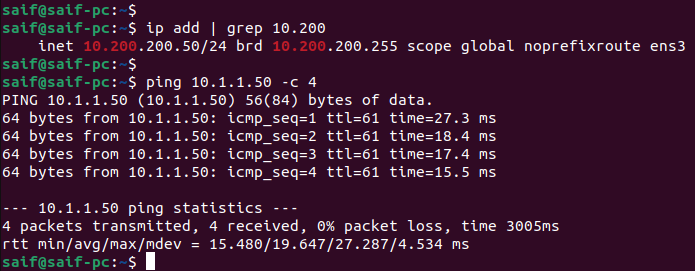
10. Test the communication through the IPsec tunnel.
You may initiate communication from the HQ site to the branch two subnets and as you can see we are able to ping both the subnets from the HQ site.

The same is true at the branch locations as well, we are able to ping the HQ subnet from the two subnets at the branch location.
Subnet 1.

Subnet 2.
We have setup the IPsec tunnel using the command line successfully, it is important that you take a look at the policy ids and route sequence number while creating them, if you are not careful you would end up replacing them with existing policies or routes that would mess up the configuration.