
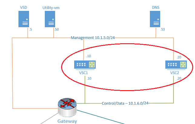
In our last section of the Nuage sdwan lab setup, we had installed VSD, which is the nuage networks VNS management plane. In this section of the lab guide, we would go ahead and install a SD-WAN controller known as VSC (Virtual Service Controller.)
Wha is Nuage VSC ?
VSC is the Nuage SDN’s controller, which guide or inform the data plane on how to send and receive data on the network. In our lab the NSG would be the data plane and always talking to VSC controller for the control plane information.
We will be using two SDN controllers for high availability. One would be acting as primary, and the other one would be as secondary.
Both the VSC’s are BGP EVPN peered so it can share its connected NSG’s mac address and IP addresses.
Let’s go ahead and start the VSC installation lab now, by following the below steps.
- Prerequisite
- Nuage VSC installation.
- Primary VSC configuration.
- Installation of secondary SD-WAN controller for high availability.
- VSC-2 Configuration
- NTP configuration
- BGP peering between VSC’s
- Encrypt XMPP and Openflow
1. Prerequisite
- The VSC has two interfaces, one for the management and others for control. We had already created both networks during the part 2 underlay network setup.
- VSC qcow2 image.
- And other prerequisite that we had mentioned on the part 1.

2. Nuage VSC installation
The nuage SD-WAN controller known as VSC is based on Alcatel lucent SR OS and most of the command that works with the SR OS would work with the VSC’s as well.
For the Nuage VSC installation, we are going to use the XML file that comes along with the software package. All you got to do is modify the XML according to your environment and define it.
Step1. Extract and move the vsc.xml and vsc_singledisk.qcow2 image to the virtualization image folder /var/lib/libvert/images
Below you can download the sample VSC XML file in txt format, once downloaded the file, change the extension from txt to XML.
Step2. Edit the vsc.xml file in notepad and make changes to below.
- Name of the VM: VSC1
<name>vsc1</name> - Update the source file destination path. In my case, I had created a vsc1 subfolder and moved the VSC VM image to it.
<source file='/var/lib/libvirt/images/vsc1/vsc_singledisk.qcow2'/> - Change the interfaces that VSC is going to use for its network.
<interface type='bridge'>
      <source bridge='mgmt5'/>
      <model type='virtio'/>
      <address type='pci' domain='0x0000' bus='0x00' slot='0x03' function='0x0'/>
    </interface>
    <interface type='bridge'>
      <source bridge='cntrl6'/>
      <model type='virtio'/>
      <address type='pci' domain='0x0000' bus='0x00' slot='0x04' function='0x0'/>
    </interface>
Step3. Let’s create the VSC1 VM
#virsh define vsc.xml
Domain vsc1 defined from vsc1.xml
- Configure VM to autostart:
#virsh autostart vsc1
Domain vsc1 marked as autostarted
This would start the VSC automatically every time the host reboots, similar to startup programs in windows.
- Start the VSC:
#virsh start vsc1
Domain vsc1 started
3. Primary VSC configuration
From now on we are going to call primary VSC as VSC-1 and secondary as VSC-2.
- Login to the VSC using the below credentials.
Username: admin
Password: admin
a. Change primary VSC hostname
By default the VSC name is “vm1” Change the hostname by using the command
configure system name vsc-1
b. VSC-1 BOF configuration
BOF (Boot On File) is where you configure most of your management configurations. Which include management IP, DNS, and management static routes, etc. Let’s configure them now.
- Assign the Management IP address.
To navigate to the Boot Options File context, enter“bof<Enter>” and the prompt would indicate a change to the bof context:
*vsc-1>bof#
- Enter the command below to configure the IP address
vsc-1>bof#
address 10.1.5.10/24
- check VSC network connectivity:
Ping the default gateway, and you may notice the ping command usability is a little different here since we have two networks on a single VSC.
- To ping management network you should use
Ping router “management “
*A:vsc-1# ping router "management" 10.1.5.1
PING 10.1.5.1 56 data bytes
64 bytes from 10.1.5.1: icmp_seq=1 ttl=255 time=1.04ms.
64 bytes from 10.1.5.1: icmp_seq=2 ttl=255 time=0.936ms.
64 bytes from 10.1.5.1: icmp_seq=3 ttl=255 time=0.928ms.
64 bytes from 10.1.5.1: icmp_seq=4 ttl=255 time=1.30ms.
---- 10.1.5.1 PING Statistics ----
4 packets transmitted, 4 packets received, 0.00% packet loss
round-trip min = 0.928ms, avg = 1.05ms, max = 1.30ms, stddev = 0.000ms
*A:vsc-1#
Note: If you are on the control network you could use
“ping and the IP”, like how you would do on other routers. or
Ping router “control” IP
- Configure Primary DNS
vsc-1>bof#primary-dns 10.1.5.53
- Try to ping the DNS IP, and you would get no response
*A:vsc-1>bof# ping router "management" 10.1.5.53
PING 10.1.5.53 56 data bytes
No route to destination. Address: 10.1.5.53, Router: management
No route to destination. Address: 10.1.5.53, Router: management
No route to destination. Address: 10.1.5.53, Router: management
No route to destination. Address: 10.1.5.53, Router: management
No route to destination. Address: 10.1.5.53, Router: management
---- 10.1.5.53 PING Statistics ----
5 packets transmitted, 0 packets received, 100% packet loss
*A:vsc-1>bof#
- To get a response, configure static routes for the management IP network.
Multiple static-route commands can be issued for the Management IP interface. A static route is added for all network (0.0.0.0/1 )with the next hop of 10.1.5.1 which is the default gateway, with the command below:
*A:vsc-1>bof#static-route 0.0.0.0/1 next-hop 10.1.5.1
*A:vsc-1>bof#static-route 128.0.0.0/1 next-hop 10.1.5.1
- Try pinging the DNS server IP again now, as you can see you would get a response this time.
*A:vsc-1>bof# ping router "management" 10.1.5.53
PING 10.1.5.53 56 data bytes
64 bytes from 10.1.5.53: icmp_seq=1 ttl=63 time=0.456ms.
64 bytes from 10.1.5.53: icmp_seq=2 ttl=63 time=0.409ms.
64 bytes from 10.1.5.53: icmp_seq=3 ttl=63 time=0.540ms.
64 bytes from 10.1.5.53: icmp_seq=4 ttl=63 time=0.558ms.
^C
ping aborted by user
---- 10.1.5.53 PING Statistics ----
4 packets transmitted, 4 packets received, 0.00% packet loss
round-trip min = 0.409ms, avg = 0.490ms, max = 0.558ms, stddev = 0.000ms
*A:vsc-1>bof#
- Now let’s go ahead and add the domain name for VSC.
VSC-1>bof#dns-domain getlabsdone.com
- We have configured the bof file successfully let’s save them using the command save when you are at bof.
*A:vsc-1>bof# save
Writing BOF to cf1:/bof.cfg ...
OK
Completed.
*A:vsc-1>bof#
i. VSC-1 final BOF configuration looks like below
*A:vsc-1# show bof
===============================================================================
BOF (Memory)
===============================================================================
    primary-image         cf1:\timos\cpm.tim
    primary-config        cf1:\config.cfg
    address               10.1.5.10/24 active
    primary-dns           10.1.5.53
    dns-domain            getlabsdone.com
    static-route          0.0.0.0/1 next-hop 10.1.5.1
    static-route          128.0.0.0/1 next-hop 10.1.5.1
    autonegotiate
    duplex                full
    speed                 100
    wait                  3
    persist               off
    no li-local-save
    no li-separate
    no fips-140-2
    console-speed         115200
===============================================================================
*A:vsc-1#
- Save the configure and reboot the VSC using the reboot command
admin save
admin reboot
c. VSC-1 Control and system interface
We had configured the management interface for VSC under BOF. We are now going to configure control/data as well as system interface IP’s.
Let’s verify the current configuration by entering the show router interface
*A:vsc-1# show router interface
===============================================================================
Interface Table (Router: Base)
===============================================================================
Interface-Name                   Adm         Opr(v4/v6)  Mode    Port/SapId
   IP-Address                                                    PfxState
-------------------------------------------------------------------------------
control                          Up          Down/Down   Network A/2:0
   -                                                             -
system                           Up          Down/Down   Network system
   -                                                             -
-------------------------------------------------------------------------------
Interfaces : 2
===============================================================================
*A:vsc-1#
Nothing configured yet, I am going to configure the control IP as below.
*A:vsc-1# configure
*A:vsc-1>config#
*A:vsc-1>config# router interface "control"
*A:vsc-1>config>router>if# address 10.1.6.10/24
*A:vsc-1>config>router>if# no shutdown
*A:vsc-1>config>router>if# back
*A:vsc-1>config>router#
Let me go ahead and configure the system IP as well, this I have to use it to establish BGP EVPN peering between the VSC’s.
interface "system"
*A:vsc-1>config>router>if# address 10.10.10.1/32
*A:vsc-1>config>router>if#exit
We can verify the configuration that I just made, as you can see both the control and the system IP is up.
*A:vsc-1# show router interface
===============================================================================
Interface Table (Router: Base)
===============================================================================
Interface-Name                   Adm         Opr(v4/v6)  Mode    Port/SapId
   IP-Address                                                    PfxState
-------------------------------------------------------------------------------
control                          Up          Up/Down     Network A/2:0
   10.1.6.20/24                                                  n/a
system                           Up          Up/Down     Network system
   10.10.10.1/32                                                 n/a
-------------------------------------------------------------------------------
Interfaces : 2
===============================================================================
*A:vsc-1#
Add a static route for the VSC router to send all traffic to the default gateway.
*A:vsc-1>config>router#static-route 0.0.0.0/0 next-hop 10.1.6.1
Save the VSC configuration
*A:vsc-1# admin save
Writing configuration to cf1:\config.cfg
Saving configuration ... OK
Completed.
A:vsc-1#
d. Adding VSC-1 to the VSD
As I discussed earlier, VSD talks to VSC using the XMPP protocol. You need to add the VSD in VSC as below.configure vswitch-controller xmpp-server vsd.getlabsdone.com
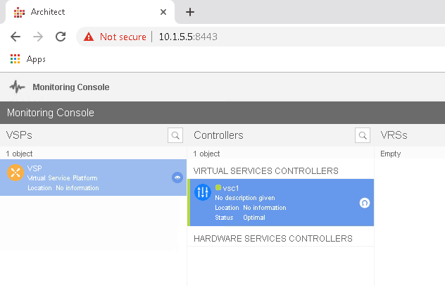
i. Check VSC-1 connected to VSD
Once you added the XMPP-Server, you could see the VSC has added to the VSD by entering the command ‘show vswitch-controller vsd’
*A:vsc-1# show vswitch-controller vsd
===============================================================================
Virtual Services Directory Table
===============================================================================
User Name                       Uptime             Status
-------------------------------------------------------------------------------
[email protected]/nuage   0d 20:01:34        available
-------------------------------------------------------------------------------
No. of VSD's: 1
===============================================================================
*A:vsc-1#
We can also confirm the same on the VSD Architect. Awesome!

4. Installation of secondary SD-WAN controller for high availability
To install the secondary VSC, follow the below steps.
Step1. Create a folder called vsc2 in /var/lib/libvirt/images/ mkdir /var/lib/libvirt/images/vsc2
Step2. Upload the VSC image to the new folder.
Step3. Edit the vsc.xml file and modify the value as below
- Name of the VM: VSC2
<name>vsc2</name> - Update the source file destination path
<source file='/var/lib/libvirt/images/vsc1/vsc_singledisk.qcow2'/> - Change the interfaces that VSC is going to use for its network. We need to add two interfaces just like before.
<interface type='bridge'>
      <source bridge='mgmt5'/>
      <model type='virtio'/>
      <address type='pci' domain='0x0000' bus='0x00' slot='0x03' function='0x0'/>
    </interface>
    <interface type='bridge'>
      <source bridge='cntrl6'/>
      <model type='virtio'/>
      <address type='pci' domain='0x0000' bus='0x00' slot='0x04' function='0x0'/>
    </interface>
Step4. Start the VSC installation.virsh define vsc2.xml
Step 5. Make VSC autostartvirsh autostart vsc2
Step6. Start the VSCVirsh start vsc2virsh start vsc2
This command should power on the vsc2, and you can further do the configuration changes.
5. VSC-2 Configuration
We have now installed VSC2, its time for us to configure the VSC2 and bring it to the SD-WAN network.
a. Change secondary VSC hostname
A:vm1># configure system  name vsc-2
\admin save
Writing configuration to cf1:\config.cfg
Saving configuration ... OK
Completed.
A:vsc-2#
b. VSC-2 BOF configuration
Just like how we have made changes to the bof configuration on VSC1, you can modify the bof configuration for VSC2.
vsc-2>bof#address 10.1.5.20/24
vsc-2>bof#primary-dns 10.1.5.53
vsc-2>bof#dns-domain getlabsdone.com
vsc-2>bof#static-route 0.0.0.0/1 next-hop 10.1.5.1
vsc-2>bof#static-route 128.0.0.0/1 next-hop 10.1.5.1
vsc-2>bof# save
Writing BOF to cf1:/bof.cfg ... OK
Completed.
vsc-2>bof#
i. VSC-2 final BOF configuration looks like below
A:vsc-2# show bof
===============================================================================
BOF (Memory)
===============================================================================
    primary-image         cf1:\timos\cpm.tim
    primary-config        cf1:\config.cfg
    address               10.1.5.20/24 active
    primary-dns           10.1.5.53
    dns-domain            getlabsdone.com
    static-route          0.0.0.0/1 next-hop 10.1.5.1
    static-route          128.0.0.0/1 next-hop 10.1.5.1
    autonegotiate
    duplex                full
    speed                 100
    wait                  3
    persist               off
    no li-local-save
    no li-separate
    no fips-140-2
    console-speed         115200
===============================================================================
A:vsc-2#
c. VSC2 Control and system interface
- Control interface.
*A:vsc-2# configure
*A:vsc-2>config#
*A:vsc-2>config# router interface "control"
*A:vsc-2>config>router>if# address 10.1.6.20/24
*A:vsc-2>config>router>if# no shutdown
*A:vsc-2>config>router>if# back
*A:vsc-2>config>router#
- And system IP
interface "system"
*A:vsc-2>config>router>if# address 10.10.10.2/32
*A:vsc-2>config>router>if#no shutdown
- Verification
*A:vsc-2# show router interface
===============================================================================
Interface Table (Router: Base)
===============================================================================
Interface-Name                   Adm         Opr(v4/v6)  Mode    Port/SapId
   IP-Address                                                    PfxState
-------------------------------------------------------------------------------
control                          Up          Up/Down     Network A/2:0
   10.1.6.20/24                                                  n/a
system                           Up          Up/Down     Network system
   10.10.10.2/32                                                 n/a
-------------------------------------------------------------------------------
Interfaces : 2
===============================================================================
*A:vsc-2#
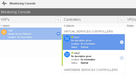
d. Adding VSC-2 to the VSD
Just like we added the XMPP for VSC1 go ahead and add it to VSC2 as well.
You must be able to see the secondary VSC in VSD now.

6. NTP configuration
You can enable NTP on both VSC’s to sync with VSD.
To configure the NTP service in VSC enters the command below.
Here NTP server is VSD, not our main NTP server.
configure system time ntp
server 10.1.5.5
no shutdown
exit
7. BGP peering between VSC’s
Finally, we got both our nuage VSC’s added to the VSD. We can configure the BGP peering between VSC’s now.
With BGP EVPN peering between the VSC’s, it can share the NSG’s MAC and IP information to each other. That way, when the primary controller goes down, you still have connectivity to the second one with the same information.
a. Adding static routes on the VSC’s
We would be BGP peering with VSC’s system IP address, hence from both VSC side, each system IP’s should be reachable, add a static route for VSC system IP reachability.
i. Static route on VSC1
static-route 10.10.10.1/32 next-hop 10.1.6.20
ii. Static route on VSC2
static-route 10.10.10.2/32 next-hop 10.1.6.10
iiii. verify the connectivity
After adding the static routes you should be able to reach each VSC’s system IPs. let’s ping the VSC2 system IP from VSC1 and vice versa.
VSC1
*A:vsc-1# ping 10.10.10.2
PING 10.10.10.2 56 data bytes
64 bytes from 10.10.10.2: icmp_seq=1 ttl=64 time=0.821ms.
64 bytes from 10.10.10.2: icmp_seq=2 ttl=64 time=0.419ms.
64 bytes from 10.10.10.2: icmp_seq=3 ttl=64 time=0.481ms.
64 bytes from 10.10.10.2: icmp_seq=4 ttl=64 time=0.505ms.
64 bytes from 10.10.10.2: icmp_seq=5 ttl=64 time=0.477ms.
---- 10.10.10.2 PING Statistics ----
5 packets transmitted, 5 packets received, 0.00% packet loss
round-trip min = 0.419ms, avg = 0.540ms, max = 0.821ms, stddev = 0.143ms
*A:vsc-1#
VSC2
A:vsc-2# ping 10.10.10.1
PING 10.10.10.1 56 data bytes
64 bytes from 10.10.10.1: icmp_seq=1 ttl=64 time=0.734ms.
64 bytes from 10.10.10.1: icmp_seq=2 ttl=64 time=0.430ms.
64 bytes from 10.10.10.1: icmp_seq=3 ttl=64 time=0.501ms.
64 bytes from 10.10.10.1: icmp_seq=4 ttl=64 time=0.781ms.
64 bytes from 10.10.10.1: icmp_seq=5 ttl=64 time=0.424ms.
---- 10.10.10.1 PING Statistics ----
5 packets transmitted, 5 packets received, 0.00% packet loss
round-trip min = 0.424ms, avg = 0.574ms, max = 0.781ms, stddev = 0.152ms
A:vsc-2#
That looks good, and we verified the system IP reachability from each VSC, now let’s go ahead and configure the BGP EVPN peering using VSC system IP’s.
b. VSC BGP EVPN configuration
ii. VSC1 BGP configuration
*A:vsc-1# configure
*A:vsc-1>config# router
*A:vsc-1>config>router# autonomous-system 65100
*A:vsc-1>config>router# bgp
*A:vsc-1>config>router>bgp$ group vsc
*A:vsc-1>config>router>bgp>group$ family evpn
*A:vsc-1>config>router>bgp>group$ peer-as 65100
*A:vsc-1>config>router>bgp>group$ neighbor 10.10.10.2
*A:vsc-1>config>router>bgp>group>neighbor$ no shutdown
*A:vsc-1>config>router>bgp>group>neighbor$ exit
ii. VSC-2 BGP configuration
A:vsc-2# configure
A:vsc-2>config# router
A:vsc-2>config>router# autonomous-system 65100
A:vsc-2>config>router# bgp
A:vsc-2>config>router>bgp$ group vsc
A:vsc-2>config>router>bgp>group$ family evpn
A:vsc-2>config>router>bgp>group$ peer-as 65100
A:vsc-2>config>router>bgp>group$ neighbor 10.10.10.1
A:vsc-2>config>router>bgp>group>neighbor$ no shutdown
A:vsc-2>config>router>bgp>group>neighbor$ exit
c. VSC BGP verification
You can type the command “show router BGP summary” that would show VSC BGP EVPN peering status.
i. VSC-1 BGP
*A:vsc-1# show router bgp summary
===============================================================================
 BGP Router ID:10.10.10.1       AS:65100       Local AS:65100
===============================================================================
BGP Admin State         : Up          BGP Oper State              : Up
Total Peer Groups       : 1           Total Peers                 : 1
Total BGP Paths         : 5           Total Path Memory           : 680
Total IPv4 Remote Rts   : 0           Total IPv4 Rem. Active Rts  : 0
Total McIPv4 Remote Rts : 0           Total McIPv4 Rem. Active Rts: 0
Total IPv6 Remote Rts   : 0           Total IPv6 Rem. Active Rts  : 0
Total IPv4 Backup Rts   : 0           Total IPv6 Backup Rts       : 0

Total Supressed Rts     : 0           Total Hist. Rts             : 0
Total Decay Rts         : 0

Total VPN Peer Groups   : 0           Total VPN Peers             : 0
Total VPN Local Rts     : 0
Total VPN-IPv4 Rem. Rts : 0           Total VPN-IPv4 Rem. Act. Rts: 0
Total VPN-IPv6 Rem. Rts : 0           Total VPN-IPv6 Rem. Act. Rts: 0
Total VPN-IPv4 Bkup Rts : 0           Total VPN-IPv6 Bkup Rts     : 0

Total VPN Supp. Rts     : 0           Total VPN Hist. Rts         : 0
Total VPN Decay Rts     : 0

Total L2-VPN Rem. Rts   : 0           Total L2VPN Rem. Act. Rts   : 0
Total MVPN-IPv4 Rem Rts : 0           Total MVPN-IPv4 Rem Act Rts : 0
Total MDT-SAFI Rem Rts  : 0           Total MDT-SAFI Rem Act Rts  : 0
Total MSPW Rem Rts      : 0           Total MSPW Rem Act Rts      : 0
Total FlowIpv4 Rem Rts  : 0           Total FlowIpv4 Rem Act Rts  : 0
Total RouteTgt Rem Rts  : 0           Total RouteTgt Rem Act Rts  : 0
Total McVpnIPv4 Rem Rts : 0           Total McVpnIPv4 Rem Act Rts : 0
Total EVPN Rem Rts      : 0           Total EVPN Rem Act Rts      : 0
===============================================================================
BGP Summary
===============================================================================
Neighbor
                   AS PktRcvd InQ  Up/Down   State|Rcv/Act/Sent (Addr Family)
                      PktSent OutQ
-------------------------------------------------------------------------------
10.10.10.2
                65100       6    0 00h01m47s 0/0/0 (IPv4)
                            6    0           0/0/0 (evpn)
-------------------------------------------------------------------------------
*A:vsc-1#
ii. VSC-2 BGP
A:vsc-2# show router bgp summary
===============================================================================
 BGP Router ID:10.10.10.2       AS:65100       Local AS:65100
===============================================================================
BGP Admin State         : Up          BGP Oper State              : Up
Total Peer Groups       : 1           Total Peers                 : 1
Total BGP Paths         : 5           Total Path Memory           : 680
Total IPv4 Remote Rts   : 0           Total IPv4 Rem. Active Rts  : 0
Total McIPv4 Remote Rts : 0           Total McIPv4 Rem. Active Rts: 0
Total IPv6 Remote Rts   : 0           Total IPv6 Rem. Active Rts  : 0
Total IPv4 Backup Rts   : 0           Total IPv6 Backup Rts       : 0

Total Supressed Rts     : 0           Total Hist. Rts             : 0
Total Decay Rts         : 0

Total VPN Peer Groups   : 0           Total VPN Peers             : 0
Total VPN Local Rts     : 0
Total VPN-IPv4 Rem. Rts : 0           Total VPN-IPv4 Rem. Act. Rts: 0
Total VPN-IPv6 Rem. Rts : 0           Total VPN-IPv6 Rem. Act. Rts: 0
Total VPN-IPv4 Bkup Rts : 0           Total VPN-IPv6 Bkup Rts     : 0

Total VPN Supp. Rts     : 0           Total VPN Hist. Rts         : 0
Total VPN Decay Rts     : 0

Total L2-VPN Rem. Rts   : 0           Total L2VPN Rem. Act. Rts   : 0
Total MVPN-IPv4 Rem Rts : 0           Total MVPN-IPv4 Rem Act Rts : 0
Total MDT-SAFI Rem Rts  : 0           Total MDT-SAFI Rem Act Rts  : 0
Total MSPW Rem Rts      : 0           Total MSPW Rem Act Rts      : 0
Total FlowIpv4 Rem Rts  : 0           Total FlowIpv4 Rem Act Rts  : 0
Total RouteTgt Rem Rts  : 0           Total RouteTgt Rem Act Rts  : 0
Total McVpnIPv4 Rem Rts : 0           Total McVpnIPv4 Rem Act Rts : 0
Total EVPN Rem Rts      : 0           Total EVPN Rem Act Rts      : 0
===============================================================================
BGP Summary
===============================================================================
Neighbor
                   AS PktRcvd InQ  Up/Down   State|Rcv/Act/Sent (Addr Family)
                      PktSent OutQ
-------------------------------------------------------------------------------
10.10.10.1
                65100       3    0 00h00m08s 0/0/0 (IPv4)
                            3    0           0/0/0 (evpn)
-------------------------------------------------------------------------------
A:vsc-2#
8. Encrypt XMPP and Openflow
There is XMPP connection from the VSC to VSD and the Openflow connection between the VSC to NSG’/VRS’s. By default those connections are not encrypted and we are going to encrypt both of them now.
Step 1. First install the vsc certificate and keys to the vsc.
- type show vswitch-controller xmpp-server
- Note down the username of that connected to the VSD.
# show vswitch-controller xmpp-server
===============================================================================
XMPP Server Table
===============================================================================
XMPP FQDN                       Last changed since State
 User Name
-------------------------------------------------------------------------------
vsd.getlabsdone.com             0d 00:19:15        Functional
 525400754d61
-------------------------------------------------------------------------------
No. of XMPP server's: 1
===============================================================================
#
- Enter the below script in VSD that would generate and upload the VSC certificate and keys into VSC.
[root@vsd ~]#/opt/vsd/ejbca/deploy/certMgmt.sh -a generate -u 525400754d61 -c 525400754d61 -d vsd.getlabsdone.com -f pem -t server -o csp -s [email protected]:/
- You would be able to see the certificates and keys under the vsc on the drive cf1:\
A:vsc-1# file dir
Volume in drive cf1 on slot A is SROS VM.
Volume in drive cf1 on slot A is formatted as FAT32
Directory of cf1:\
11/16/2019  09:46a                1135 525400754d61-CA.pem
11/16/2019  09:46a                1703 525400754d61-Key.pem
11/16/2019  09:46a                1581 525400754d61.pem
11/16/2019  09:46a                4647 525400754d61Cert.pem
11/16/2019  09:12p                 789 bof.cfg
06/13/2018  08:14p                 190 bof.cfg.1
11/16/2019  09:11p                2492 bootlog.txt
11/16/2019  09:15p                3690 config.cfg
11/16/2019  09:12p                3578 config.cfg.1
06/13/2018  08:14p                   0 config.cfg.2
06/13/2018  08:14p                  62 nvram.dat
11/16/2019  09:11p                 319 nvsys.info
06/13/2018  08:14p      <DIR>          syslinux/
06/13/2018  08:14p      <DIR>          timos/
              12 File(s)                  20186 bytes.
               2 Dir(s)              1036636160 bytes free.
A:vsc-1#
Step2. Creation of TLS profile.
I am creating a TLS profile called “gld-tls-profile-01”
A:vsc-1>config>system>security# tls-profile gld-tls-profile-01 create
*A:vsc-1>config>sys>sec>tls-profile>$ own-key cf1:\525400754d61-Key.pem
*A:vsc-1>config>sys>sec>tls-profile>$ own-certificate cf1:\525400754d61.pem
*A:vsc-1>config>sys>sec>tls-profile>$ ca-certificate cf1:\525400754d61-CA.pem
*A:vsc-1>config>sys>sec>tls-profile>$ no shutdown
*A:vsc-1>config>sys>sec>tls-profile>$ exit
*A:vsc-1>config>system>security# exit
*A:vsc-1>config>system# exit
*A:vsc-1>config#
Step3. Apply the TLS profile you created for both XMPP and openflow.
A:vsc-1# configure
A:vsc-1>config# vswitch-controller
A:vsc-1>config>vswitch-controller# xmpp
A:vsc-1>config>vswitch-controller# xmpp tls-profile "gld-tls-profile-01"
*A:vsc-1>config>vswitch-controller# open-flow tls-profile "gld-tls-profile-01"
*A:vsc-1>config>vswitch-controller#
Step4. Verification.
we just encrypted the traffic between the VSC and the VSD, and the Openflow session we are going to create with NSG.
- When you check the VSD status, you could see its been reset since close to 2 mins
A:vsc-1# show vswitch-controller vsd
===============================================================================
Virtual Services Directory Table
===============================================================================
User Name                       Uptime             Status
-------------------------------------------------------------------------------
[email protected]/nuage   0d 00:01:16        available
-------------------------------------------------------------------------------
No. of VSD's: 1
===============================================================================
- And when you look into the xmpp-server details you could see that it is using xmpp encryption type as TLS.
A:vsc-1# show vswitch-controller xmpp-server detail
===============================================================================
XMPP Server Table
===============================================================================
XMPP FQDN          : vsd.getlabsdone.com
XMPP User Name     : 525400754d61
Last changed since : 0d 00:01:29
State              : Functional
IQ Tx.             : 10                 IQ Rx.             : 10
IQ Error           : 0                  IQ Timed Out       : 0
IQ Min. Rtt        : 0                  IQ Max. Rtt        : 20
IQ Ack Rcvd.       : 10
Nuage Updates Rcvd.: 0                  VSD Updates Rcvd.  : 2
Nuage Msg Tx.      : 1                  Nuage Msg Rx.      : 1
Nuage Msg Ack. Rx. : 1                  Nuage Msg Error    : 0
Nuage Msg Min. Rtt : 20                 Nuage Msg Max. Rtt : 20
Nuage Sub Tx.      : 2                  Nuage UnSub Tx.    : 0
Nuage Msg Timed Out: 0
Encryption Type    : tls
===============================================================================
A:vsc-1#
Step6. Follow the same steps on the VSC2 to encrypt its traffic between the VSD and VSC2.
Now that we have installed the controller, let’s go ahead and install the nuage proxy server.