I have covered what is VXLAN and the differences between the overlay and underlay network here, in this blog we are going to take a look at the overlay and underlay in action using nuage sd-wan lab.
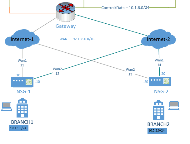
The underlay network topology.
Below is the actual underlay network, The Branch 1 NSG is connected to two WAN links both from internet 1 and 2 respectively, so is the NSG2 at the branch-2.

How does the NSG1 at the branch one talks to the NSG2 at Branch2 ?
It uses VXLAN tunneling mechanism between these two branches and passes the overlay traffic.
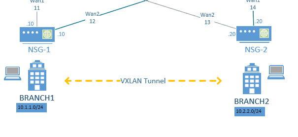

The LAN side of these branches which is the overlay is not aware of the underlay network.
The connection between the Branch-1 and Branch-2 LAN side would go via the VXLAN tunnel.
What if you add one more branch to the topology?
All the branch networks become a full mesh topology and start to send traffic with each other.
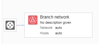
As you can see in the diagram above, we are going to use two overlay subnets in this lab, like below.
10.1.1.0/24 – Branch1
10.2.2.0/24 – Branch2
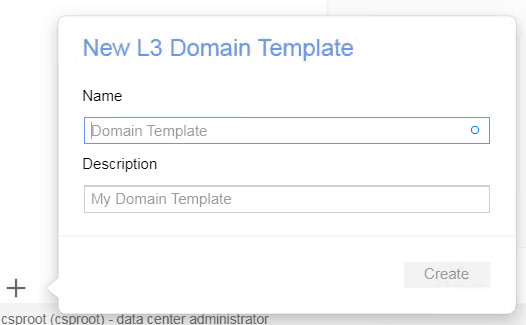
Follow the below steps to create the overlay network in Nuage SD-WAN.
- Goto the Organisation and click on Networks
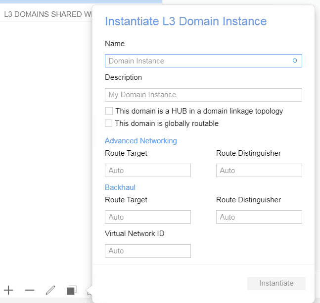
- Click on the plus icon to create L3 Domain, I am naming it as L3 Domain.

- Drag and drop the zone templates to the domain.

- Select the domain you just created and click on the Instantiate domain from down bottom left. I just gave the name Network.
- Now you can start drag and drop the subnet to the branch networks, eventually it would look like below.
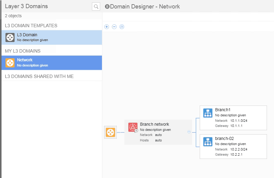
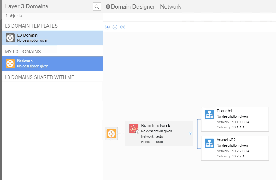
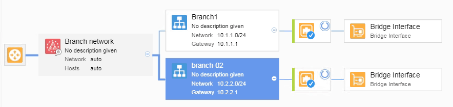
- You need to attach the NSG’s to the subnet by attaching Bridge Vport.

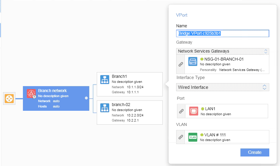
- You just attached the branch-1 LAN side to the overlay, you may do the same steps for the Branch-2 as well.
- We successfully added the NSG to the overlay network.

Attaching the end-user machine on the Overlay.
We have already created a VLAN 111 and 222 for Branch-1 and branch-2 LAN side respectively on the underlay gateway as well as on the KVM hosts where we are going to deploy the branch hosts.
I have also deployed Centos and Ubuntu 19.04 for Branch1 and Branch2 respectively, let’s connect both to our network.
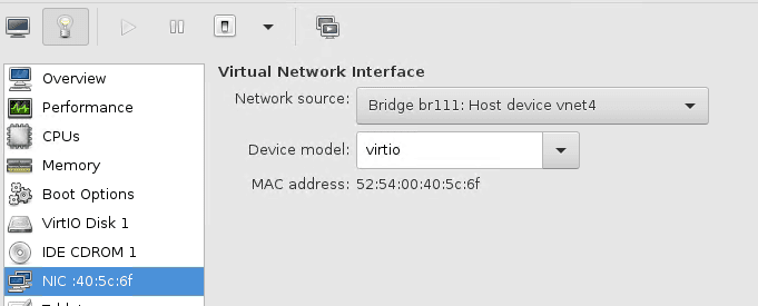
- Going to use Centos as the branch-1 machine, Open the Centos VM and click on properties. On the network select Bridge interface ‘br111’ for the host and apply the changes.
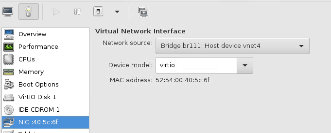
- Do the same thing on the ubuntu host which represents Branch-2 as well, but use br222 for the second host instead of br111.
Now, will you be able to connect the hosts between?
Of course not as we have not configured the IP address on these hosts.
Let’s configure the IP for the hosts from the VSD using the DHCP.
Configuration of DHCP in Nuage VNS
- goto the enterprise, click on Network, select the subnet and click on the DHCP icon.
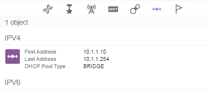
- Create the DHCP scope like below, I intentionally left the first ten IP addresses from the scope.
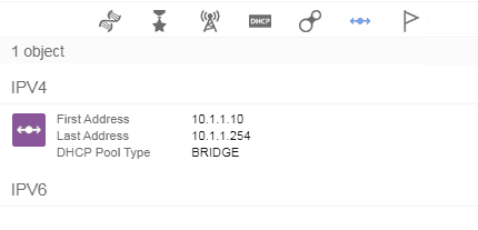
- Do the same thing for the second subnet as well.
- Now you connect the network in the hosts you would get IP address from those DHCP scopes.
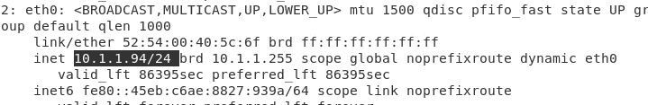
As you can see below, I got an IP address 10.1.1.94 for the Centos from branch-1.

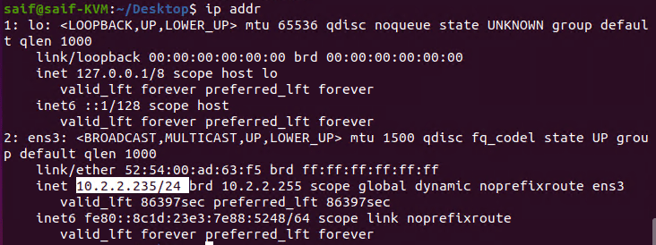
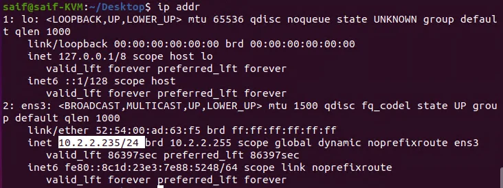
And got 10.2.2.235 for the Ubuntu from Branch-2.
Allow Overlay communication
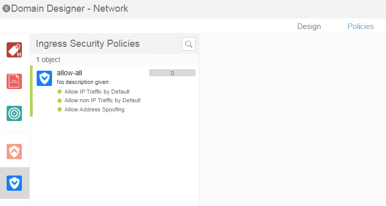
In order for the branch to branch communication to happen, you need to allow the ACL policy in VSD.
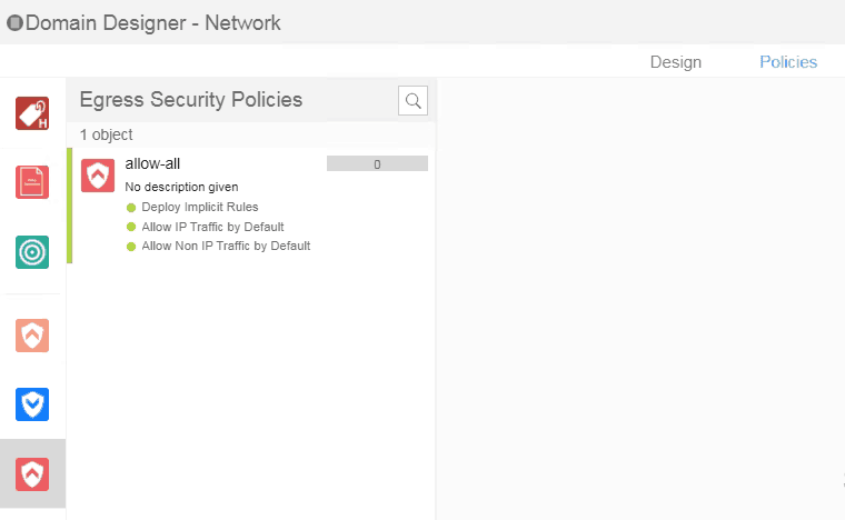
- Login to the VSD and click on Policies, create an ingress security policy to allow-all like below.

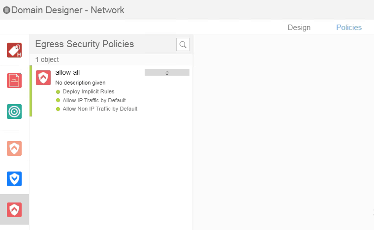
- Do the same thing for the Egress security policies as well.
Overlay Communication verification
Lets start pinging the host’s machines.
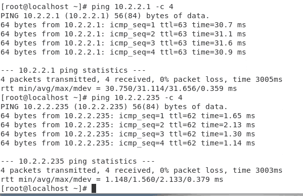
As you can see I can ping the Branch-2 gateway IP 10.2.2.1 as well as the host IP which is 10.2.2.235

Lets verify the same from branch-2
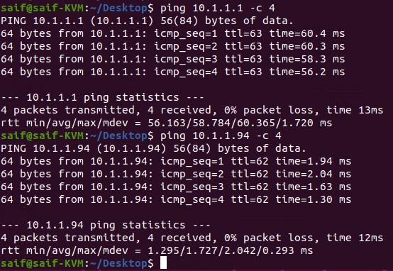
Yes, I can ping the gateway 10.1.1.1 as well as the hosts 10.1.1.94 here as well.

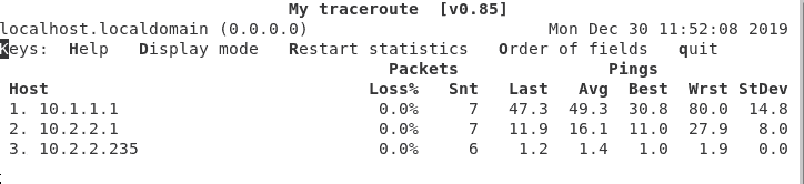
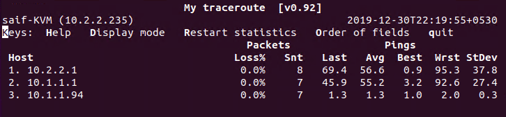
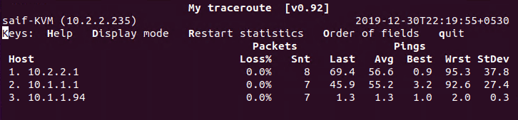
Finally let’s also verify the traceroute of these packets.
When I ran my traceroute with the command mtr 10.1.1.94, you get the below output.
It is just overlay devices and there is no underlay networks in it.
Same on the other side as well with the command mtr 10.2.2.235